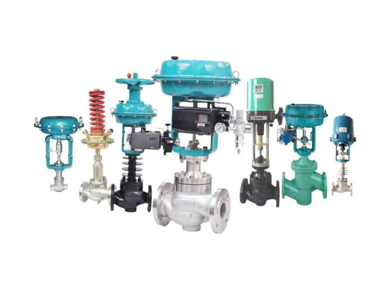
Control valves regulate and control the flow, pressure, the temperature of a flowing fluid, such as gas, steam, water, or the chemical mixture by opening or closing internal passages. They control the amount of flow in processes. The valve stem moves, altering the size of passage, and this increases, decrease or holds steady flow.
The control valve has three main parts :
Valve body – in which the modulating element, a globe, plug, ball, or butterfly is contained
Valve actuator -which moves the valve’s modulating elements, such as ball or butterfly
Valve positioner-which ensure the valve has reached the required degree of opening, this overcomes the problem of friction and wear.
The control valve body can be categorized as below, the body part of the control valve stays in contact with the products. To handle the temperature, pressure, and chemistry of medium.
1. Globe control valve
1.1 Single-seat globe control valve body
1.2 Double seat globe control valve body
1.3 Balanced plug cage globe control valve body
1.4 Cage guided globe control valve body
1.5 Three-way valve body
2. Angle valve
2.1 Cage style valve body
2.2 Disk stack style valve body
3. Diaphragm valve
4. Rotary valves
4.1 Butterfly valves body
4.2 V-notch ball control valve body
4.3 Eccentric-disk control valve body
4.4 Eccentric-plug control valve body
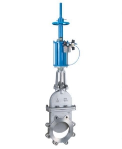
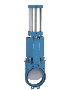
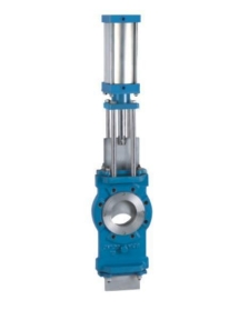
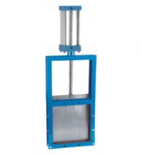
5. Sliding cylinder valves
5.1 Directional control valve
5.2 Spool valve
5.3 Piston valve
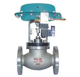
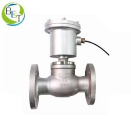
6. Air-operated valve
6.1 Air-operated valve
6.2 Relay valve
6.3 Air-operated pinch valve
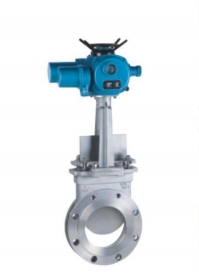
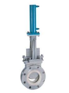
The valve actuator is used to move the valve stem, it opens or closes the control valve according to the change required in the flow. We can have linear or rotary actuators, depending on the valve’s body type. For example, a butterfly Valve requires a rotary actuator, a globe valve usually work with a linear actuator. The rate of flow through the valve depends on the pressure difference between the inlet and outlet
There are three different systems to move happen -pneumatic, hydraulic, and electrical. Pneumatic actuators convert air pressure to a linear or rotary movement. Hydraulic do the same with liquids instead of air. And electric actuators use motors to convert electrical energy into mechanical torque. All the systems work forward and backward, or indirect or reverse actions. In direct actions, the input will push the actuator down the valve stem, and the spring with push it back up. For reverse actions, the input pushes the valve stem up, and the spring pushes it back down.
The valve positioner is to deliver pressurized air to the valve actuator. Positioners are usually used when a control valve requires throttling action. A positioner requires position feedback from the valve stem or shaft and delivers pneumatic pressure to the actuator to open and close the valve. The positioner must be mounted on or near the control valve assembly. There are three main types of positioners, depending on the type of control signal, the diagnostic capability, and the communication protocol: pneumatic analog and digital.
Processing units may use a pneumatic pressure signal as the control setpoint to the control valves. The pressure is usually modulated between 20.7 to 103 Kpa ( 3 to 15 psi) to move the valve from 0 to 100% position. In a common pneumatic positioner, the position of the valve stem or shaft is compared with the position of a bellows that receives the pneumatic control signal. When the input signal increases, the bellows expand and moves a beam. The beam pivots about an input axis, which moves a flapper closer to the nozzle. The nozzle pressure increases, which increases the output pressure to the actuator through a pneumatic amplifies replay. The increased output pressure to the actuator causes the valve stem to move. Stem movement is fed back to the beam employing a cam. As the cam rotates, the beam pivots about the feedback axis to move the flapper slightly away from the nozzle. The nozzle pressure decreases and reduces the output pressure to the actuator. Stem movement continues, backing the flapper away from the nozzle until equilibrium is reached. When the input signal decreases, the bellows contracts and the beam pivots about the input axis to move the flapper away from the nozzle. Nozzle pressure decreases and the relay permits the release of the diaphragm causing pressure to the atmosphere, which allows the actuator stem to move upward. Through the cam, stem movement is fed back to the beam to reposition the flapper closer to the nozzle. When equilibrium conditions are obtained, stem movement stops, and the flapper is positioned to prevent any further decrease in actuator pressure.
The second type of positioner is an analog I/P positioner. Most modern processing units use a 4 to 20mA DC signal to modulate the control valve. This introduces electronics into the position design and requires that the positioner convert the electronic current signal into a pneumatic pressure signal. In a typical analog I/P positioner, the converter receives a DC input signal and provides a proportional pneumatic output signal through a nozzle/flapper arrangement. The pneumatic output signal provides the input signal to the pneumatic positioner. Otherwise, the design is the same as the pneumatic positioner