Troubleshooting is a systematic approach to troubleshooting often used to find and fix problems with complex machines, electronic devices, computers, and software systems. The first step in most troubleshooting methods is to gather information about the issue, such as unwanted behavior or a lack of expected functionality.
The primary troubleshooting objectives are to figure out why something doesn’t work as intended and provide a solution to resolve the issue.
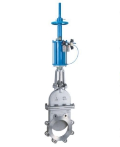
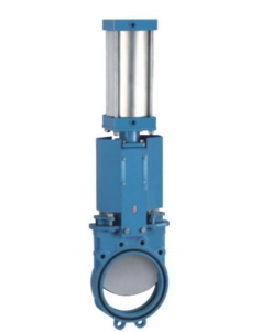
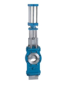
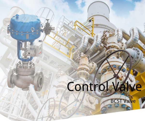
What is a Control Valve?
Control valves are programmed to handle and regulate pressure and flow.Therefore, they can automatically do the job and eliminate the need for you to monitor the system constantly. Instead, you can choose the correct control valve for the specific desired pressure. It is interesting to know that control valves are also called final control elements in automatic control terminology due to the process control valves operating within their system.
Control valves keep the variables of a flowing fluid, like chemical compounds, steam, gas, and water, close to the desired set point by manipulating the fluid. The control signal, which could be either electronic or pneumatic, manipulates the CV and changes its location, accurately controlling the flowing fluid and reaching profitable production requirements. It also helps save money by reducing unnecessary costs.
Three Main Parts of Control Valve
Valve Actuator.
This part is responsible for moving the valve’s modulating element.
Valve Body.
This part contains modulating elements such as butterflies or a globe.
Valve Positioner.
This unit is responsible for checking the valve’s position and ensuring its opening degree is the same as the desired number.
What are the Common Control Valve Issues, and how to solve them?
- The first step in diagnosing your control valve is visually checking each component. If you find any issues, correct them first.
- The air supply from the air filter regulator (AFR) to the valve positioner or solenoid valve, whichever is applicable, should be checked for proper operation. If there is no air in this area, check the isolation valve status in the air supply header. If found closed, open it to provide access to the AFR.
- AFR set pressure is the maximum pressure applied to the control valve. It would be best if you verified this value against the datasheet, which will list it as either psi or bar.
- The recommended air supply pressure is 3.0 bar. If the air supply pressure exceeds this, valve movement will be sluggish. If the air supply pressure is more significant than 3.0 bar, then this may cause damage to the actuator. Then adjust the air pressure to the recommended settings.
- To open the control valve, issue the command: Open Control Valve. To close the control valve: Issue the order: Close Control Valve. If the valve does not move, check for voltage at the field cable connection. If no voltage is present, check for proper relationships between the DCS system and the field cabinet by tracing them back from the field cabinet to a marshaling cabinet.
- Checking the fuse healthiness in the marshaling cabinet is a quick and easy way to check your communications equipment’s power supply. If you find that a blown a fuse has damaged your communications equipment, you should replace it with a new fuse of the same rating. If this doesn’t solve the problem, you can check your cables for damage.
- If you find that the resistance of your cable pair is higher than usual, it could indicate that the cable pair is faulty. To test this, check the resistance of each cable pair and compare it to the others. If your resistances are significantly higher than other cable pairs, replace your existing cable pair with a healthy spare. It will help ensure that you have enough voltage for your control valve to operate correctly.
- The control valve is a mechanical system; the best way to check it is by doing the stroke test. To do the stroke test, we need to give 0 to 100% command from the control system to operate the control valve and do the valve stroke checking test. Next, we will check for control valve feedback on the graphics during this process. It is essential because it shows how well or poorly the valve works under pressure or vacuum.
- If the valve stroke is correct according to the system command, but the feedback is not accurate, feedback setup/configuration is required. On the other hand, if the valve stroke is not ok and feedback is good, the problem may be due to a bad wire connection or a sensor on the solenoid.
- There are two main valve feedback designs: open and close. Honest feedback is when you have a dial that can be turned to adjust the valve’s position, while immediate feedback is when there are no adjustable controls and the valve’s position cannot be altered. You’ll want to use an open or close feedback design of 0% to 100% full analog feedback (depending on your control valve design). If your issue is in an analog-based system, then your control valve calibration may help you solve the problem.
- The control valve may not make any stem movement if the control system is not healthy. If the control system sends commands to the valve but is not received, check for interlocks and permissive in the PLC or DCS logic.
- If there is an issue in the control valve stroke, then the calibration will solve the issue. In addition, calibrating the control valve will ensure that your level of accuracy is at its peak. It is because calibrating the control valve ensures you better understand your system and how it works. It can help you identify problems before they become serious issues requiring costly repairs or replacements.
- You can use a digital multimeter (DMM) to check the stroke. It will allow you to measure the voltage applied to the valve positioner. You can also check this with the control system by giving different commands. If there is still an issue with the stroke, check the mA to the input of the valve positioner. It will give you an idea of how much power is used by all components involved in this process. Again, give different commands from the control system and recheck your readings. There might be an issue with your PLC/DCS analog output channel that could be causing problems with your valve positioner, but this is very rare.
- If the valve positioner works correctly, you should not need to replace it. However, if you have doubts about its functioning, you should replace it and perform a calibration. After calibration, you should check the stroke of the control valve again and ensure it is correct.
- The quick exhaust valve, air volume booster, trip valve, and vent port are all essential components of a steam boiler. Therefore, they should be checked regularly to ensure they are working correctly and not blocked by debris or other objects. If any of these accessories are blocked, it may result in an issue with water flowing out of the boiler. This can cause overheating or loss of pressure in the system. If this happens, it’s recommended that they be replaced immediately so your safety is never compromised.
- If you’re replacing a faulty item, check the part number on your receipt and ensure that you order the correct replacement. If you don’t have spares, then repair them and install them.
- If the control valve operation is still not working correctly, remove all tubing from the system and check the control valve movement by applying external air directly to the actuator.
- If the actuator is passing and the filter is clean, there may be a problem with the valve body. Do an overhauling of the valve body to see if it can be fixed.
- The control valve should move with minimal resistance. The air pressure set on the nameplate or datasheet of the control valve should be used as a guide.
- The control valve is a fail-safe mechanism, meaning that it will close when it detects that the pressure in the system is too high.
- Decoupling the actuator from the valve body is a common way to restore movement to an idle control valve.
- If the actuator response is still functioning correctly, there will likely be an issue with the valve body. The valve body is lowered for inspection and overhaul.
- The control valve is of linear type movement, meaning that it moves in a straight line. Therefore, you will also need to install a dropping valve on it. Before dropping the control valve, make sure you have made proper markings.
- After reinstalling the control valve and doing a stroke check, you should be able to see that your water pressure is now higher than it was before.