Pneumatic control valves as one of the most commonly used valves in the production process automation adjustment system. Many users in the selection of models usually easy to mess up the “hands and feet.”
Because different working conditions corresponding to the regulating valve products are other, so choosing a separate regulating valve is the key to controlling the process parameters for various diseases.
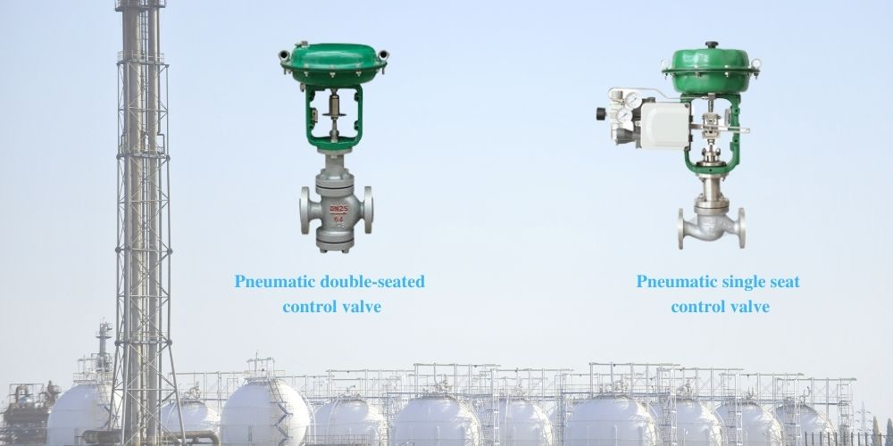
For example, the most common pneumatic double-seated control valves, due to their different structural forms, the corresponding use of the occasion is not the same!
1. Single Seat Control Valves
The single-seat control valve is one of the most common control valves and is also known as a straight-through single-seat valve.
1.1 Structure
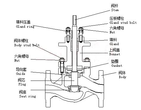
The single seat control valve consists of a valve body, spool, guide sleeve, upper valve cover, upper cover plate, stem, and packing.
Structural Characteristics
The structure of the single-seated control valve is characterized by a single spool and a single seat. The upper cover is used for pressing the packing. The upper cover is bolted to the valve body and is used for the central positioning of the stem and spool.
The valve seat and the upper cover are used to ensure the central positioning of the spool and the heart. And when the spool moves, it changes the flow area of the fluid, changing the manipulation variable from the face to achieve the function of regulating the fluid flow.
The valve stem and spool are fixed with connecting or interference fit pins. The spool guidance in the diagram is top-guided. Some single-seated control valves are top and bottom guided to improve guidance accuracy. Some small flow spherical control valves are often seat-guided.
1.1.2 The Role of Single-Seat Control Valves
The spool is moved by the stem when the actuator is displaced in a straight line.
When the spool moves down, the reduced fluid flow area is called a positive body valve. Conversely, the fluid flow area increases are known as a reverse body valve. It makes it easy to flip the position of the spool about the stem so that the positive body valve is changed to a negative body valve or vice versa.
Only positive body valves are available for D.N. < 25 mm single-guided straight-through single-seat valves, and a counter-acting actuator is required for gas-open control.
1.2 Features
1.2.1 Small Leakage.
Single-seat control valves are easy to achieve tight sealing and shut-off.
For example, we can use metal-to-metal hard seals, metal-to-tetrafluoroethylene, or other soft composite seals. Standard leakage is rated at a flow coefficient of 0.01% C.C.
1.2.2. The Allowed Differential Pressure is slight.
For example, the allowable differential pressure of a DN100 valve is only 120 kPa.
1.2.3. Small Flow Coefficient.
For example, the flow coefficient of a DN100 straight-through valve is only 100.
1.2.4. Fluid Medium.
As the fluid medium on the spool of the significant thrust, the imbalance force is large. Therefore, large diameter applications should not be used in high differential pressure.
1.2.5. Spool Role
The flow characteristics of the control valve are achieved using differently shaped spools.
2. Double-seated Control Valves
2.1 Structure
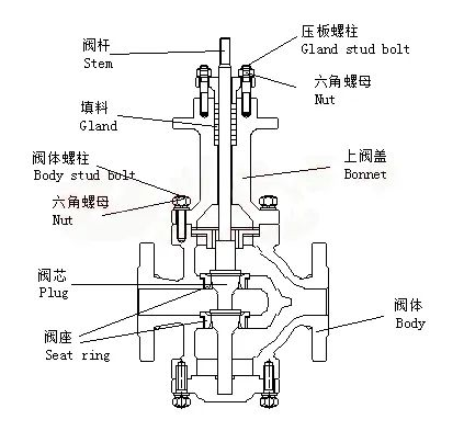
The two-seat control valve consists of the valve body, spool, guide sleeve, valve seat, upper valve cover, upper cover plate, valve stem, packing, etc.
characteristics
Only two spools and two seats characterize the structure of the double-seated control valve. After the two spools and hearts, the fluid flows from the left side of the diagram to the right side of the outflow.
As the upward thrust of the spool and the downward thrust of the spool are basically balanced, the unbalanced force on the whole spool is small.
2.2 Features
2.2.1 Small Balancing Force
Double-seated control valves are subject to small unbalance forces and large permissible pressure drops. For example, the DN100 double-seated control valve allows a differential pressure of 280 kPa.
2.2.2 Large Flow Coefficient.
Compared with other control valves of the same caliber, double-seated control valves can flow through more fluid, the same caliber double-seated valve flow coefficient than the single-seated valve flow coefficient of about 20% to 50%.
For example, a DN100 double-seated valve has a flow coefficient of 160. Therefore, the double-seated valve can be used with a more miniature thrust actuator to obtain the same flow coefficient.
2.2.3 Installation
Positive and negative body valves are easy to retrofit, as the double-seated valves are double-guided at the top and bottom. Therefore, we can change the positive body valve to a negative body valve and the opposing body valve to a positive one by simply installing the spool and seat in reverse—no need to change the type of actuator from positive to negative acting.
The double-seated valve construction shown can be completed by simply reversing the valve body and connecting it to the stem. Guides can replace the top and bottom guides for the valve seat.
2.2.4 High Leakage.
A double-seated valve’s top and bottom spool cannot be guaranteed to close simultaneously. As a result, double-seated valves have a large leakage volume, which can be even more significant due to the different linear expansion of the material.
However, in recent years it has been reported that some double-seated control valves with a unique overall structure can achieve leakage levels I ~ V.
2.2.5 Poor Scouring Resistance.
The valve flow path is complex. In high-pressure differential applications, the high-pressure fluid scouring is more serious, and in the high-pressure differential, caused by the fluid flash and cavitation, aggravating the scouring of the valve body.
Therefore, the double-seated valve is not suitable for high-pressure differential applications. Due to the complex flow path, it is also unsuitable for controlling fiber-containing media and highly viscous fluids.
2.2.6 The Role of the Valve Spool
The flow characteristics of control valves are achieved using differently shaped spools.