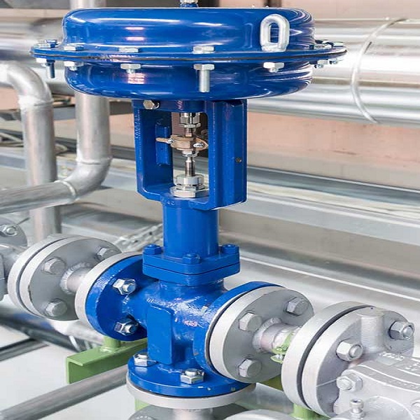
What is the Pneumatic control diaphragm valve?
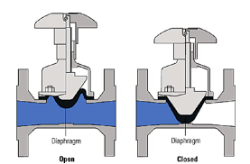
The pneumatic control diaphragm valve is a unique form of shut-off valve that appeared in the 1920s. Its opening and closing member is a diaphragm made of soft material, which is used to separate the inner cavity of the valve body from the internal cavity of the bonnet and the driving parts. The most prominent feature of the pneumatic control diaphragm valve is that the diaphragm separates the lower body cavity from the upper bonnet cavity so that the valve stem, valve flap, and other parts are located above the diaphragm are not subject to media corrosion. It eliminates the need for a packing seal structure and does not produce media leakage.
Add Your Heading Text Here
Pneumatic diaphragm control valves are the most widely used type of final control element. Other last control elements include metering pumps, regulating baffles and louvered baffles (a variant of the butterfly valve), fan blades with variable slope, current regulating devices, and motor positioning devices that are different from valves. Despite the widespread use of pneumatic diaphragm control valves, no other unit in the regulating system probably requires as little maintenance as it does. In many systems, control valves are subjected to more severe operating conditions such as temperature, pressure, corrosion, and contamination than other components. However, when it controls the flow of process fluids, it must operate satisfactorily and generate the minimum amount of maintenance.
What are the differences between the pneumatic control diaphragm valve and the pneumatic diaphragm control valve?
The focus of the two is different. The former refers to the structure of the valve, which is the body plus the diaphragm for corrosion protection. The latter refers to the construction of the actuator, which is the diaphragm head of the actuator.
The two actuators are the same, but the valve body and the internals differ.
The specific differences are shown in the following areas.
1. Working Principle
Pneumatic Control diaphragm valve:
The working principle of the pneumatic control diaphragm valve is that when compressed air is allowed to enter the left diaphragm media chamber through the air distribution valve, the diaphragm piece is pressurized and pushed outwards. It forms a compression stroke. The medium in the pressure feed section is then forced to leave the left outer diaphragm chamber through the ball spool valve seat and the manifold and then flows out from the outlet side of the pump. The outlet position can be at the top, bottom, or side (depending on the customer’s requirements for opening or changing the direction of the inlet and outlet). The outlet can be located at the top or bottom of each outer diaphragm chamber or share a standard inlet and outlet pipe. The diaphragm chambers are connected by a suction and outlet connection. The pump is self-priming to achieve suction of the medium. When the left diaphragm chamber diaphragm is pushed out under pressure, the diaphragm link shaft inside the intermediate drags the right diaphragm back inwards and fills with fluid. After this cycle is complete, the air distribution valve automatically changes position so that the air is switched to the other diaphragm chamber. The cycle is repeated in the opposite direction, and both diaphragm chambers thus exhibit alternating compression strokes and media pumping action.
In practice, the link shaft in the air distribution valve drives the alternating action of the control diaphragm to increase pressure. After each stroke, the air distribution valve automatically changes the position of the air supply so that we can switch the air to the other side of the diaphragm chamber. It results in alternating suction and pressure strokes between the two diaphragm chambers. The diaphragm is compressed in the liquid chamber to do the work.
Pneumatic diaphragm control valve:
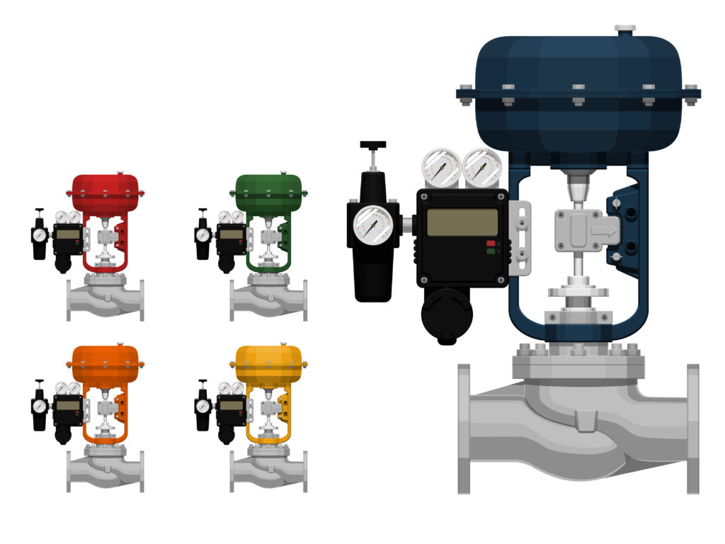
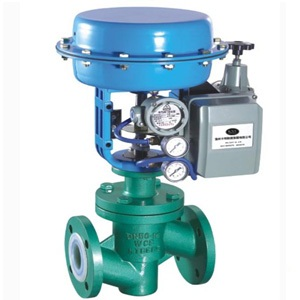
Pneumatic diaphragm control valves use compressed air as the power source and cylinders as the actuator, with the help of electrical valve positioners, converters, solenoid valves, position-keeping valves, and other accessories to drive the valve. It enables switching or proportional adjustment. And by receiving the control signal from the industrial automation control system to complete the adjustment of the pipeline medium flow, pressure, temperature, and other process parameters. The pneumatic diaphragm control valve is characterized by simple control, fast response, and intrinsic safety. It does not require additional explosion-proof measures.
2. Structure
Pneumatic Control diaphragm valve:
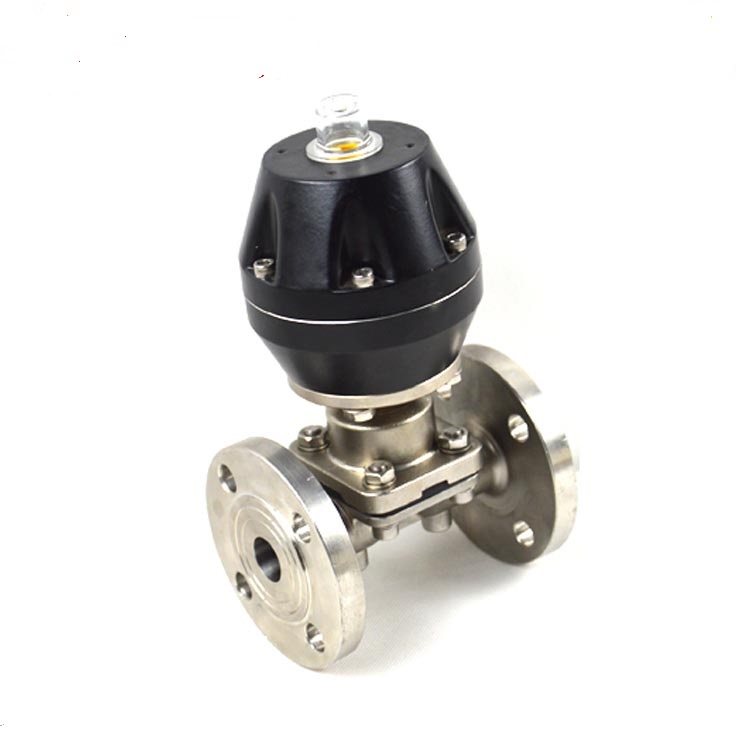
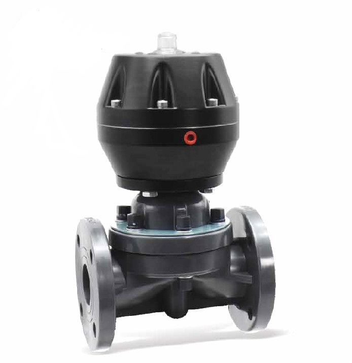
The pneumatic control diaphragm valve is constructed in a very different form from the standard valve. It relies on a soft rubber mold or plastic membrane to control the movement of the fluid. Its opening and closing piece is a diaphragm made of soft material, which separates the valve body’s inner cavity from the valve cover and the driving parts, so it is called a diaphragm valve. The valve body is lined. The diaphragm valve body is lined to bring out its corrosion resistance properties.
Pneumatic diaphragm control valve:
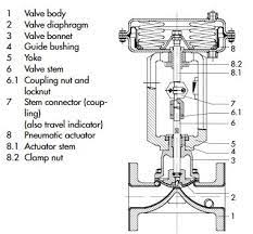
Pneumatic diaphragm control valves are composed of a pneumatic diaphragm actuator and a valve body. The valve body comprises an air chamber, film, thrust disc, spring, pushrod, adjusting nut, valve position scale, stem, spool, seat, stuffing box, valve body, valve cover, and bracket.
Depending on the operating conditions, you can add optional accessories. For example, accessories such as electrical valve positioners, converters, solenoid valves, position-keeping valves, etc., can be used to drive the valve to achieve switching or proportional adjustment. Thus receiving the control signal from the industrial automation control system to complete the adjustment of various process parameters such as flow, pressure, and temperature of the pipeline medium.
3. Classification
Pneumatic Control diaphragm valve:
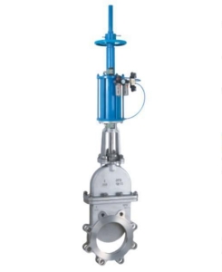
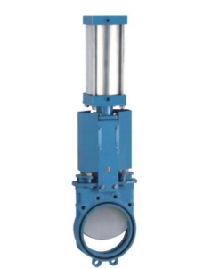
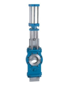
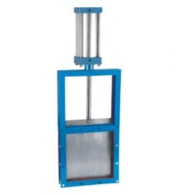
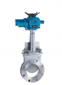
Diaphragm valves can be divided into six types according to their structure: Roof type, direct type, globe type, straight type, gate type, and right angle type. The connection form is usually a flange connection. In addition, pneumatic control diaphragm valves can be divided into normally open, normally closed, and reciprocating types.
Pneumatic diaphragm control valve:
Pneumatic diaphragm control valves can be divided into nine categories according to their principle, function, and structure. They are single-seat control valves, double-seat control valves, sleeve control valves, angle control valves, three-way control valves, diaphragm valves, butterfly valves, ball valves, and eccentric rotary valves. The first six types are straight strokes, and the last three are angular strokes. It is the most commonly used classification method in China and internationally. A variety of unique products are in the nine types of products based on the improvement of the variant.
4. Advantages
Pneumatic Control diaphragm valve:
The pneumatic control diaphragm valve has two main advantages.
One is that the valve does not require a separate stem packing seal structure. Instead, the diaphragm plays a sealing role on the stem while cutting off the medium.
The second is that the flexible diaphragm closes reliably. Even dirty liquids can do a good cut-off. Therefore, the manipulation mechanism and the media channel are entirely isolated. It makes the pneumatically controlled diaphragm valve not only suitable for the food industry and the pharmaceutical and hygiene industry but also for some difficult to convey media and dangerous media.
Pneumatic diaphragm control valve:
The pneumatic diaphragm control valve has the advantages of compact structure, lightweight, sensitive action, slight pressure drop loss, large valve capacity, precise flow characteristics, and easy maintenance. We can also use it in demanding operating conditions. The pneumatic diaphragm control valve comprises a multi-spring pneumatic film actuator and a low flow resistance precision single-seat control valve body. The multi-spring actuator used for the control valve has the advantages of low height and lightweight and accessible equipment.
5. Features
Pneumatic Control diaphragm valve:
The most important feature of the pneumatic diaphragm control valve is its construction. It is a set of thin, hemispherical metal films clamped into the valve body, which acts as a barrier between the stem and the fluid. Valve closure is achieved by the stem head and the metal film pressing the valve disc against the seat. The valve is opened using an internal spring. The valve disc rises when the stem is raised and out of contact with the membrane. The characteristic lift of this valve is much smaller than that of a typical valve, as the stroke of the valve is equal to the stroke of the membrane.
To overcome the resistance losses caused by the low lift, the valve seat and flow area are larger than a standard valve. Therefore, it is intended to obtain a larger flow rate. Due to the larger seat of this valve, the force is much greater than in a normal valve. So that sufficient sealing force is obtained on the valve disc, as there is no direct contact between the stem and the disc. The disc, therefore, does not pass through the stem and leave its seat. Thus, the valve is suitable for one-way flow with differential pressure, and the medium is usually from “below the seat.” In use, however, we should avoid a large amount of backflow to prevent affecting the closing of the valve.
The diaphragm is made of rubber, plastic, and other soft seals, with a better seal. However, as the diaphragm is a perishable part, we should replace it regularly depending on the characteristics of the medium.
Restricted by the diaphragm material, pneumatic diaphragm control valves are suitable for low pressure and relatively low-temperature occasions.
Pneumatic diaphragm control valve:
1)The input and output characteristics of the actuator of the pneumatic diaphragm control valve show a linear relationship, i.e., the output displacement is linearly related to the input signal pressure. Some counter-acting actuators also install a valve position indicator on the top of the diaphragm box to display the valve position. The stroke of the domestic pneumatic diaphragm control valve actuator is 10mm, 16mm, 25mm, 40mm, 60mm, 100mm, etc.
2)The effective area of the actuator’s diaphragm is proportional to the thrust.
3)The structure of positive and negative acting actuators is the same. They are composed of an upper diaphragm cover, lower diaphragm cover, film diaphragm, pushrod, spring, adjusting parts, bracket, travel display plate, etc.
4)The main difference between the structure of positive and reverse acting actuators is that the input signal of the reverse acting actuator is in the lower part of the membrane box, and the push rod leading out is also in the lower part. Due to the excellent sealing of the membrane sheet, no sealing is required at the stem lead-in.
5) we can use the adjustment of the adjusting piece to change the initial spring force and thus the actuator’s thrust.
6) We can add a self-locking device to the pneumatic diaphragm control valve to achieve self-locking and position-keeping of the control valve.
7)Pneumatic diaphragm control valve can add a valve positioner to achieve valve position detection and feedback. And it can also improve the control performance.
8) We can add a pneumatic diaphragm control valve to the displacement conversion device. It can convert linear displacement to angular displacement for rotating the valve body.
9) We can add a pneumatic diaphragm control valve to the handwheel mechanism. In case of automatic control failure, We can use the handwheel for downgrading operations to improve system reliability.
6. Application
Pneumatic Control diaphragm valve:
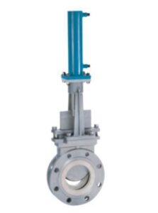
The pneumatic control diaphragm valve consists of an actuator and a diaphragm valve. Diaphragm valve body circulation smooth, throttling elements for the resilient diaphragm valve, the valve cover without packing letter. As a result, the valve’s flow capacity is larger than that of a standard control valve, and there is no leakage. A positive and negative actuator achieves the air opening and closing action.
Pneumatic control diaphragm valves are used in the pharmaceutical industry for hygienic and aseptic processes. We can control the top pneumatic actuator through a solenoid valve. The valve is ideally suited for fluid control and on/off tasks. In addition, the diaphragm provides the body seal and the seat seal.
The pneumatic control diaphragm valve is suitable for regulating highly viscous fluids, suspended particles, fibrous media, and toxic and corrosive media.
Pneumatic diaphragm control valve:
Pneumatic diaphragm control valves are widely used in various pipelines, water treatment, natural gas, electric power, chemical, petrochemical, oil, paper, mining, liquefied gas, food, municipal and mechanical equipment, electronic industry, urban construction, and other fields.
Pneumatic diaphragm control valves are suitable for applications where small leakage is allowed, and the pressure difference between the front and rear is not large. In addition, according to different working conditions, the pneumatic film adjustment valve has a variety of forms, such as low temperature, heat dissipation, bellows sealing type, etc.
7. Selection principles
Pneumatic Control diaphragm valve:
The pneumatic control diaphragm valve is a clamping class valve. It is mainly used for opening and closing the pipeline.
Usually, we would recommend using pneumatic control diaphragm valves under the conditions of use or in situations requiring strict sealing performance. In addition, when there is a slurry medium, wear or light structure, low-pressure cut-off (slight differential pressure) to the atmosphere, a small amount of leakage, and abrasive media, we also recommend using diaphragm valves. We also use diaphragm valves in double-position adjustment, throttling, channel indentation, low noise, cavitation, and vaporization, where the manipulation torque is small.
However, we do not choose to use diaphragm valves in high-temperature media, high-pressure media, high-pressure shut-off (high differential pressure), fast opening and closing action, and short structural length, except for metal diaphragm valves.
The choice of metal pneumatic control diaphragm valves at high temperatures and pressures is economical and effective. The valve can also be used in low-temperature, low-pressure occasions where the use of synthetic rubber diaphragm valves is not desired.
Pneumatic control diaphragm valves are generally unsuitable for use at temperatures above 60°C and in pipelines carrying organic solvents and strong oxidizing media. Using pneumatically controlled diaphragm valves in higher pressure lines is also inappropriate.
Pneumatic diaphragm control valve:
1) According to the use requirements of the selection
Different use requirements of the pneumatic diaphragm control valve have different structural forms. Pneumatic diaphragm adjustment valve mainly has a straight single-seat valve, double-seat adjustment valve, and high-pressure angle adjustment valve.
A.Straight single-seat valves have a small leakage volume, and the unbalanced force formed by the thrust of the fluid on the single-seat valve spool is large. Therefore, straight-through single-seated valves are suitable for applications requiring small leakage, small pipe diameters, and low differential pressure between the front and rear of the valve.
B.The straight-through double-seated valve has two spools in the body, which roughly cancel each other out due to the opposite direction of thrust of the fluid acting on the upper and lower spools. So the unbalanced force of the double-seated valve is minimal, allowing a large differential pressure before and after the valve. However, due to the complex flow path in the valve body, the erosion damage to the valve body is more serious when used for high differential pressure, so it is unsuitable for high viscosity, containing suspended particles or media containing fibers. In addition, due to the constraints of the processing conditions, double-seated valves up and down the two spool is not easy to close simultaneously. So when closed, it has a large leakage, primarily when used at high or low temperatures. Because of the different coefficients of thermal expansion of materials, it is more likely to cause serious leakage.
C.Angle’s high-pressure valve body is a right-angle type. It has a simple flow path, low resistance, and is subject to high-speed fluid erosion is also small. It is particularly suitable for high differential pressure, high viscosity, and fluids containing suspended particulate matter. It can also deal with vapor-liquid mixed-phase and easy flash vapor corrosion. This valve body can avoid coking, bonding, and blockage.
2)Selection according to safety
The pneumatic diaphragm control valve has two forms air-open and air-closed valves. According to different production processes and the use of security requirements, when the signal pressure interruptions regulating valve in the open or closed position, the size of the harm caused to the process production. If the valve is closed when the hazard is small, choose the air-to-open valve. When the signal pressure is interrupted, the control valve is closed. Conversely, we choose the gas closed valve.
3) According to the flow characteristics selection
We should focus on the flow characteristics in the design process of the self-control system selection of the pneumatic film control valve. Typical ideal characteristics are linear flow characteristics, equal percentage flow characteristics (logarithmic flow characteristics), fast open flow characteristics, and parabolic flow characteristics of four.
A.If the linear flow characteristics, in the case of the same relative change in the opening of the flow rate, the relative change in the value of the flow rate is large. And in the flow rate of large, the relative change in flow rate value is small. Therefore, the linear flow control valve, in the case of small opening (small load), regulation performance is not good and not easy to control. It tends to produce oscillations, so the linear flow regulating valve is unsuitable for small openings. It is also not suitable for regulating systems where the load varies considerably. It is therefore ideal for regulating systems where the load is relatively smooth and does not vary much.
B.Percentage flow characteristics of the regulating valve in the small load regulation role are weak, large load regulation role is strong. It weakens regulating when close to closing and works slowly and smoothly. However, it has a strong regulating action near the whole opening and works efficiently and effectively. To a certain extent, it can improve the quality of regulation, so it is suitable for applications where the load varies greatly. Whether in full-load or half-load production, it can play a good regulating role.
4)The choice of control valve diameter
We should calculate the required flow coefficient CV value according to the known fluid and select the appropriate regulating valve diameter according to the product technical parameters table. In calculating CV value, we should pay attention to the difference between liquid, gas, water vapor, and other vapors.
5) We should take corrosion-resistant measures for the pneumatic diaphragm control valve working under strong acid and alkali media. In the selection, we can use corrosion-resistant stainless steel or valve body all lined with PTFE to achieve the purpose of anti-corrosion.
8. Installation
Pneumatic Control diaphragm valve:
1) Preparation before installation.
A.Before installation, we should check whether the diaphragm valve specifications and materials follow the design.
B.Before installation, we need to clean up the internal sand, dust, foreign matter, and debris to avoid poor action or leakage.
C.The appropriate piping should be suspended appropriately and fixed by the regulations to avoid undue stress on the valve after installation.
D.The two flange surfaces of the piping must be aligned parallel and concentric.
E.We should install separate gaskets between the diaphragm valve and the flange.
F.Do not paint the rubber lining and diaphragm surface with grease to prevent the rubber from swelling. It will affect the service life of the diaphragm valve.
G.Valves should be stored in a dry and ventilated room, and stacking is strictly prohibited. We must seal stock diaphragm valves at both ends of the channel, and the opening and closing parts should be slightly open.
2) Installation steps.
A.Before installation, we must clean the interior of the diaphragm valve of sand, dust, foreign objects, and debris.
B.Set the auxiliary screw at the appropriate position to adjust the distance between the two flange surfaces.
C.We need to insert the diaphragm valve without touching the two flange faces while threading the remaining bolts.
D.We need to ensure that the center of the diaphragm valve is concentric with the center of the flange and that the bolts are locked repeatedly in a diagonal progressive manner until the flange face touches the end face of the valve body.
Pneumatic diaphragm control valve:
1) We should install pneumatic film adjustment valves vertically on horizontal pipelines if particular circumstances need to be installed horizontally and inclined, generally to add a support seat. It can reduce the vibration of the pipeline caused by the regulating valve open and close stuck or not in place phenomenon.
2) To prevent the aging of the regulating valve diaphragm and extend the service life, we should try to avoid high temperature, vibration, and corrosive environments during installation.
3) We should install the regulating valve near the ground or the floor to facilitate maintenance and repair. To facilitate maintenance and disassembly, we should pay attention to the regulating valve from the ground (or the floor) to leave a suitable height. For positive-acting air-opening regulating valves, the regulating valve should be sufficiently far from the ground because the spool needs to be removed from underneath the valve body during disassembly. It is something that must be considered when installing the pipeline.
4) When the control valve and the control system fail, in order not to affect production and safety accidents, we generally need to install a bypass and bypass valve. However, we cannot install the bypass valve directly above the regulating valve to avoid corrosive media leakage from the bypass valve to the regulating valve.