Control valves are the “hands and feet” of the automation in the production process. They are used to regulate the flow in the production site and are always in contact with the medium.
What kind of control valves and actuators are commonly used to control the flow? Today, we will introduce you to the actuators for the control valve which are commonly used in the production site. These actuators are most widely used at many industrial sites, such as chemical, food& beverage, industrial energy & onsite utilities,oil&gas, wastewater treatment,power Generation,pulp&paper, etc.
Today , let us introduce several actuators
1. Spring Diaphragm Pneumatic Actuators
Valve actuators are a very important and necessary part of the control valve. It provides the force physically to drive the restrict-or which is inside the valve body, then to realize the purpose to change the fluid flow. It can also be applied in other positioning elements in industrial automatic systems. The spring diaphragm pneumatic valve actuator mainly has two parts, one is a diaphragm ( a flexible membrane) which is made of rubber or neoprene, another is a spring. The membranes
Moves until there is an equation between the opposing force and the spring. In this situation, the motion stops, and the valve plug and stem which are connected with membranes will be in a balanced state. When there is no air pressure en trying, the valve stem will be pushed upward by the spring.
Usually, the pressure controller signal is between 0 to 15 psi. When the pressure signal is maximum at 15 psi, the valve stem will be forced downward. The plug position will be corresponding according to the differential pressure signal.
The air pressure of the control signal from the controller enters the actuator at the top of the housing. When it increases, there will be a force to push the diaphragm downward which can be again est the tension of a spring.
This type of control valve is capable of exerting large forces. The amount of force relies on the size of the membranes and how much air is supplied to it.
For example, if the 15 psi maximum pressure is supplied to a diaphragm which has a size of 10 inches, the actuator will provide a force of 11775 pounds to move the valve. The formula is as below
F=PA
Where :
F=force
P=pressure
A=area
F=psi*3.14 *r2
=15psi*3.14 *r2
=1177.5 pounds
There are two types of spring diaphragm pneumatic actuator:
One is direct-acting which is also said air to close. It means the air to the diaphragm pushing the actuator to move the valve stem downward. This air to close action compresses the spring which in turn pushes the actuator stem back up when the supplying pressure is decreased or lost. This will result in the valve in a fail to open position.
Direct-acting
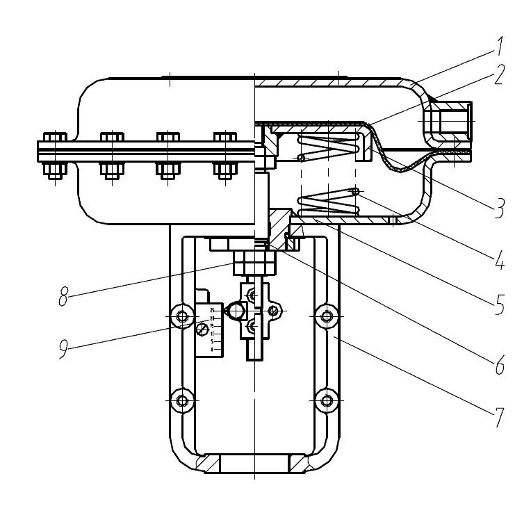
1. Up diaphragm castings 2. Diaphragm
3. Diaphragm plate 4. Spring
5. Down diaphragm castings 6. Actuator stem
7. Yoke 8. Adjust nut
9.Travel indicator
Reverse-acting
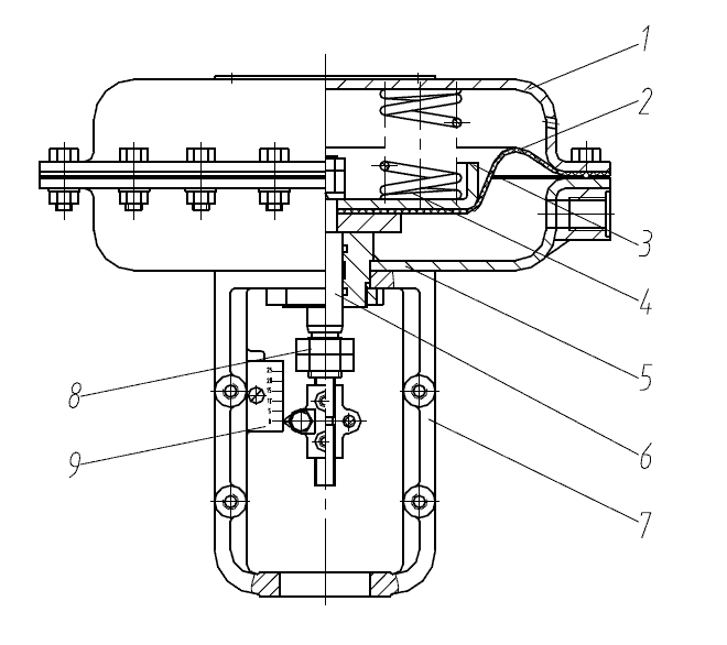
1. Up diaphragm castings 2. Diaphragm
3. Diaphragm plate 4. Spring
5. Down diaphragm castings 6. Actuator stem
7. Yoke 8. Adjust nut
9.Travel indicator
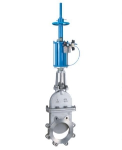
2.Piston Actuators
Working principle of piston-actuator
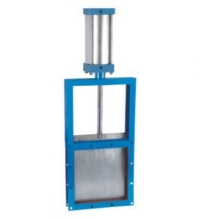
Piston actuators are mainly applied where the stroke of a diaphragm actuator would be very short or the thrust is very small, which is in air operated systems. The compressed air is applied to a solid piston contained within a solid cylinder. The pneumatic piston actuator is typically mounted to the upper master and wing valve for sequenced closure during shutdown operations.
Piston actuators can be single acting or double acting, and it can withstand higher input pressures and can offer smaller cylinder volumes, which can act at high speed.
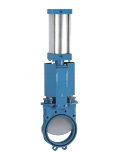
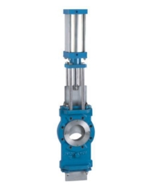
This actuator offers a reliable and cost-effective option when a robust actuator is required. It is recommended when instrument air, sweet well gas, or sour well gas is available.
To open the gate valve, the actuator supplies a downward force upon the application of pneumatic pressure from an external source. When control pressure is relieved, pressure in the valve body, aided by a compression spring in the actuator, returns the piston to its normal position.
The depressed of control pressure drives the actuator to act as a fail-safe closed device when used to reverse-acting gate valves.
The pneumatic piston actuator moves valves in differential sizes from 1/8 in through 18 in. The actuator piston is offered in various sizes between 8” and 20” to optimize the control pressures for the application.
A fast-separated bonnet that allows removal of the actuator without decompressing the control valve, which greatly saves downtime and lost production
Rising valve stem give visualizing signal of valve position
Outside safety relief device defends the actuator from over pressurization
The integral design allows easy maintenance in limited areas
Wire cutting capabilities on specific models provide fail-safe gate closure during wire-line operations
Pneumatic piston actuators
3.Hydraulic Actuator
Hydraulic Actuators supply hydraulic pressure to drive a valve body which is used in industrial process control. They are usually used where high speed and large amounts of forces are required, such as main steam system valves. The fluid used in the hydraulic actuator is highly incompressible so that pressure applied can be transmitted instantaneously to the member attached to it.
The hydraulic supply and return line is linked to the lower chamber and allows the hydraulic fluid to flow to and from the lower chamber of the actuator. The stem transmits the piston motion to a valve.
Firstly, with no hydraulic fluid pressure, the spring force keeps the valve in the closed position. As fluid enters the lower chamber, pressure in the chamber will increase accordingly.
This pressure gives a force on the bottom of the piston opposite to the force made by the spring. If the hydraulic force is more than the spring force, the piston starts to move upward, the spring presses, and the valve moves to open.
As the hydraulic pressure grows, the valve remains open. The other way around, as hydraulic oil is drained from the cylinder, the hydraulic force becomes less than the spring force, the piston moves downward, and the valve will be closed. By controlling the total amount of oil supplied or drained from the actuator, the valve can be positioned from fully open to fully closed.
The operation principles of a hydraulic actuator are similar to the pneumatic actuator. Each uses some motive force to overcome the spring force to drive the valve. Also, hydraulic actuators can be made to fail-open or fail-closed.
Advantages of Hydraulic Actuators
1. Hydraulic actuators are sturdy and durable and good performance for high force applications. They can generate forces 25 times greater than pneumatic cylinders of the same size. They can also operate in pressures of reaching 4,000 psi.
2. The hydraulic actuator can keep force and torque constant without the pump supplying more fluid or pressure due to the fluids can’t be compressed
3. Hydraulic actuators can let their pumps and motors place a suitable distance away with minimal loss of power.
Disadvantages of Hydraulic Actuators
The fluid may be a leak in hydraulic actuators the same as pneumatic actuators, loss of fluid results in less efficiency and cleanliness problems leading to possible damage to near components and areas.
The hydraulic actuators need lots of cooperated parts, including a reservoir, releasing valves, pump, motor, heat exchangers with noise reduction device