VALVE TYPES
Valves used in the oil and gas industry and for piping applications can be classified in multiple ways:
VALVES BY DISC TYPE
LINEAR MOTION: gate, globe, diaphragm, pinch, and check valves
ROTARY MOTION: butterfly, ball, plug, eccentric- and swing check valves
QUARTER TURN: devices that require approximately a quarter turn motion, from 0 to 90° of the stem to move from fully close to a fully open position or vice versa.
Oil and Gas Valve Types | Linear Motion Valves | Rotary Motion Valves |
Quarter Turn Valves |
Gate valve | x |
|
|
Globe valve | x |
|
|
Check valve |
| x |
|
Ball valve |
| x | x |
Butterfly valve |
| x | x |
Plug valve |
| x | x |
Diaphragm valve | x |
|
|
Safety valve/Pressure Relief Valve | x |
|
|
Pinch Valve | x |
|
VALVES BY BODY MATERIAL
CAST (the body is obtained by casting steel). The primary casting materials for valves are listed in this article.
FORGED (the body is manufactured by forging steel)
VALVES BY TYPE OF ACTUATION
MANUAL: the valve is operated manually, via levers, wheels, or gears;
ACTUATED: the valve is actioned via electromechanical devices, called actuators, that may be electric, pneumatic, hydraulic, and gas over oil
DESIGN VALVE
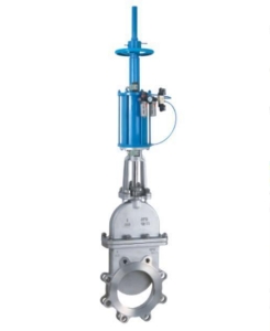
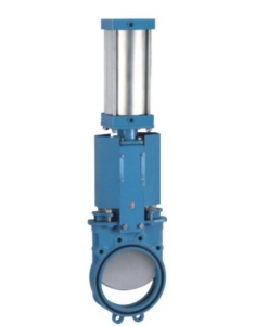
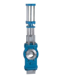
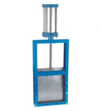
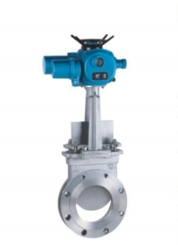
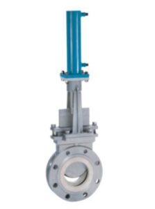
GATE VALVE: This type is most commonly used in piping and tubing applications. Gate valves are linear motion devices that open and close the fluid flow (shutoff valve). Gate valves cannot be used for throttling applications, e.g., to regulate the fluid flow (globe or ball valves should be used in this case). A gate is therefore fully opened or closed (via manual wheels, gears or electric, pneumatic and hydraulic actuators)
GLOBE VALVE: This type of valve is used to throttle (regulate) fluid flow. Globe valves can also shut off the flow, but gate valves are preferred for this function. A globe valve creates a pressure drop in the pipeline as the fluid must pass through a non-linear passageway.
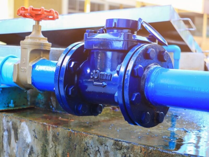
CHECK VALVE: this type of valve is used to avoid backflow in the piping system or the pipeline that could damage downstream apparatus such as pumps, compressors, etc. When the fluid has enough pressure, it opens the valve; when it comes back (reverse flow) at design pressure, it closes the valve – preventing unwanted flows.
BALL VALVE: A Ball valve is a quarter-turn valve used for shutoff application. The valve opens and closes the fluid flow via a built-in ball that rotates inside the valve body. Ball valves are the industry standard for on-off applications and are lighter and more compact than gate valves, which serve similar purposes. The two main models are floating and trunnion (side or top entry)
BUTTERFLY VALVE: This is a versatile, cost-effective valve to modulate or open/close the fluid flow. Butterfly valves are available with concentric or eccentric (double/triple) design, have a compact shape and are becoming more competitive than ball valves due to their more straightforward construction and cost.
PLUG VALVE: Plug valve is a quarter-turn valve for shutoff applications. The Romans introduced the first plug valves to control water pipelines.
SAFETY VALVE: A safety valve protects a piping arrangement from dangerous overpressures that may threaten human life or other assets. Essentially, a safety valve releases pressure when a set value exceeds.
PINCH VALVE: This type of linear motion valve can be used for throttling and shutoff application in piping applications that handle solid materials, slurries, and dense fluids. A pinch valve is equipped with a pinch tube to regulate the flow.
CONTROL VALVES: these are valves for the automation of complex petrochemical processes.
Y-STRAINERS: while not properly a valve, Y-strainers have the vital function of filtering debris and protecting downstream equipment that may be otherwise damaged
VALVE SIZES
To make sure that valves of different manufacturers are interchangeable, the face-to-face dimensions of the critical types of valves have been standardized by the ASME B16.10 specification.
ASME B16. 34: VALVE COMPLIANCE
The ASME valve B16.34 is a globally accepted standard for design, manufacture, and test valves used in the oil and gas industry. ASME B16.34 is also mentioned in the more general ASME specification ASME B31.1, “Power Piping Design.
From 1988, the scope of this standard was modified to include valves with threaded and welded ends as well as valves with flanges.
A valve complies with ASME B16 when:
- The valve body and the amplifier; hull materials meet ASME and ASTM material standards for chemistry and strength
- Body and Amp; Hull materials are heat-treated to ensure proper grain structure, corrosion resistance, and hardness.
- Wall thicknesses of the body and other pressure-containing components meet ASME B16.34 minimum values specified for each pressure class.
- NPT and SW terminal connections conform to ASME B1.20.1 or ASME B16.11.
- Rods are internally loaded and burst resistant.
- All bolts shall be ASTM grade with maximum applied stress controlled by B16.34.
- Each valve is shell tested at 1,5x rated pressure for a specific test duration.
- Each valve is tested for seat leakage in both directions for a specific test duration.
- Each valve is permanently tagged with materials of construction, operating limits, and the manufacturer’s name.
A control valve is used in the oil and gas industry to regulate the fluid flow rate in a pipeline or process (and the related process parameters such as pressure, temperature, and level) according to signals managed by a controller. The role of a flow control valve in the complex petrochemical process is vital, as the multiple loops involved in the process must be subject to strict and dynamic control to ensure that the process, overall it works as expected and produces the desired result in terms of quantity, quality and time.
The application of flow control valves has been increasing in the last years due to growing process automation in most industries.
These valves are used in irrigation systems, water treatment plants, oil and gas plants, power generation, fire prevention systems, and food processing industries by streamlining the response to changes in processes and providing more excellent safety to personnel and equipment.
A flow control valve used in the oil and gas industry can have a globe, butterfly, or ball shape and is available in different material grades and sizes. The most used type of actuator is the air-operated, as it involves less ancillary equipment (such as cabling and switchgear) than other actuators.
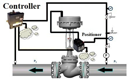
The opening and closing of the valve and its regulation are carried out under the combined effect of an electronic controller, a positioner, and the valve actuator (which can be electric, pneumatic or hydraulic).
The actuator opens and closes the control valve in response to changes in crucial process parameters, such as pressure, level, temperature, and flow. With this action, process parameters are maintained within the required target range to ensure that the process, as a whole, works as expected and produces an end product in the desired quantity and quality.
FLOW CONTROL VALVE COMPONENTS
The main components of a control valve are:
The valve body: where the modulating element is contained and operates.
The positioner is the element that controls the degree of the valve opening and is mounted on the body of the valve.
The actuator: is the device that moves the modulating element of the valve, disc or stem.
LOW CONTROL VALVE ACTUATORS
The selection of actuators is based on the rod’s required thrust and the valve’s movement.
Engineers must determine whether the schematic or piston actuator is the most appropriate type. Actuators are the primary energy source to move and position the flow control element within the valve body.
Various types are available, including pneumatic, electric, hydraulic, electro-hydraulic, and manual. Pneumatic actuators are most commonly used for control applications.
For more than a century, three types of pneumatic actuators have been considered the standard for automatic control: piston, spring-and-diaphragm, and rotary vane. The first two can be adapted for use on rotary or sliding stem valves; the latter is only used on rotary valves.
FLOW CONTROL VALVE ACCESSORIES
Typically, the selection of accessories such as positioners, transducers, boosters, solenoid valves, limit switches, handwheels and travel stops, snubbers, regulators, and transmission lines, is based on engineering specifications.
Cost is a significant factor in material selection.
Not only the cost of the material in dollars per pound but also the cost of fabrication and inspection contribute to the cost of uninstalling the valve. The installed price includes not only the cost of installation but also the cost of any damage from improper installation and fees for the inspection.
The latter includes elements such as chemical analysis of materials, radiographic and surface examination of castings and welds, and checking to see that the installed valve is correctly oriented.
The selection of the appropriate or optimum type of control valve depends on the particular study of the piping system and the condition of its fluid. Still, the size of the control valve should be such that pressure drops through it and not the drop of the pressure of the pipe is the one that controls the flow.
All valves, including steam control valves, are designed to meet an acceptable internal leakage standard (FCI / ANSI). The higher the leaks, the lower the permissible internal leakage rate.
A Class I valve will have the highest internal leak rate and generally the lowest cost, while a Class VI valve will have the lowest allowable internal leak rate. Steam valves should be specified to have a leak rate of at least Class IV. A Class IV steam control valve will maintain a long life.
FLOW CONTROL VALVES TYPES
Control valves can be categorized into two main types based on stem movement:
Linear/reciprocating motion: Globe (straight, angle, 3-way), diaphragm and pinch control valves.
Rotating stem: types of ball, butterfly, and poppet control valves. Globe control valves can be either single or double seats.
Process engineers must consider many factors to select the appropriate control valve. The general criteria to consider for selection are summarized below:
Type of control; degree of power; the degree of shutoff.
Allowable pressure drop; design temperature; design pressure.
Corrosivity of fluids; fluid erosion properties of fluids; other characteristics, such as scale or coke.
Inherent characteristics include valve Cv: degree of hazard from leakage; heat or cold conservation; cost.
As the design criteria are known, process engineers can select the correct type of control valve and related equipment, as well as the material of the valve itself.
The next step is to create a detailed specification and create a purchase specification describing the valve for suppliers.
The specification should contain, as a minimum: a description of the type of control valve (rotary, sliding); bore and pressure rating; terminal connections; type of joints in the body; specification of materials for body components, finishes, seals, and bolting; positioner and controller requirements; a reference to an industrial design standard for the type of the valve. Generally, a computerized system help engineers determine the most suitable control valve and its features based on process parameters.