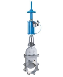
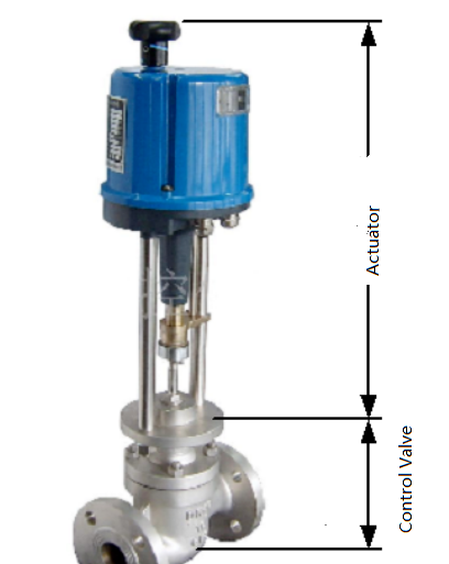
The basic structure of the electric control valve
The upper part of the electric control valve is the actuator. It accepts the 0~10mADC or 4~20mADC signal from the regulator and converts it into the corresponding linear displacement. Thus, it can push the lower regulating valve action to adjust fluid flow direction.
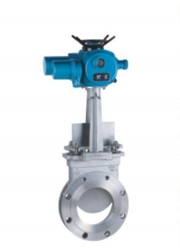
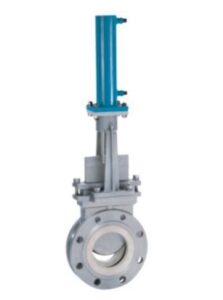
The actuator of each type of electric regulating valve is the same. Still, the. Still, the structure of the regulating valve (a regulating mechanism) has many types depending on the conditions of use. The most commonly used electric control valves are straight through the single seat and straight through the double seat.
The basic structure of the electric actuator
Its electric actuator mainly consists of mutually isolated electrical and transmission parts. The motor is an intermediate part of connecting the two isolated parts. The engine outputs torque as required by the control. It is transmitted to the trapezoidal screw through a multi-stage spur gear, transforming the torque into thrust using a thread.
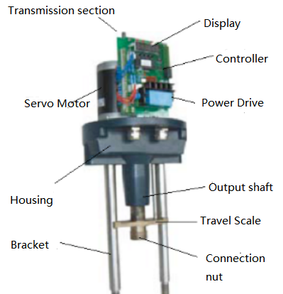
The trapezoidal screw thus transmits linear travel to the valve stem via a self-locking output shaft. The actuator output shaft has a stop ring to prevent transmission. This radial locking device of the output shaft can also be used as a dynamic position indicator.
The output shaft stop ring has a flagpole attached to it, which will run in synchronization with the output shaft. It converts the output shaft displacement into an electrical signal through a rack and pinion plate connected to the flagpole. And it can also be provided to the intelligent control board as a comparison signal and valve position feedback output. Also, the stroke of the actuator can be limited by two main limit switches on the rack and pinion plate and protected by two mechanical limits.
Working principle of the actuator
The electric actuator uses the motor as the driving source and the DC as the control and feedback signal. The schematic block diagram is as follows.
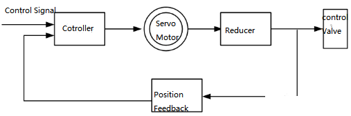
When a signal is an input to the input of the controller, this signal will be compared with the position signal. When the deviation of the two signals is greater than the specified deadband, the controller generates a power output. It drives the servo motor to rotate the output axis of the reducer in the direction of reducing this deviation until the deviation is less than the dead band. At this point, the output axis is stabilized at the position corresponding to the input signal.
Controller structure
The controller comprises the main control circuit board, sensor, operation button with LED, phase splitting capacitor, terminal block, etc. The intelligent servo amplifier is based on a special monolithic microprocessor. First, it converts the analog and valve position resistance signals into digital signals through the input loop. Then, the microprocessor displays the result and outputs the control signal after the artificial intelligence control software according to the sampling result.
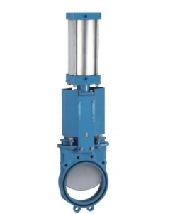
The basic structure of the control valve
The control valve is in direct contact with the regulated medium in the processing pipeline. As a result, the spool moves in the valve body, changing the flow area between the spool and the valve seat. That is, you can adjust the process parameters by changing the resistance coefficient of the valve.
The following figure gives a typical structure of straight through the single seat and straight through the double seat. It consists of the upper valve cover (or high-temperature high-temperature upper valve cover), valve body, lower valve cover, spool parts consisting of spool and stem, valve seat, packing, pressure plate, etc.
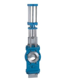
A straight single-seated valve has only one spool and one seat in the body. Its characteristics are simple structure, small leakage (even completely cut off), and small allowable differential pressure. Therefore, it is suitable for clean media requiring small leakage and slight working pressure difference. Particular attention should be paid to its allowable differential pressure in the application to prevent the valve from shutting down.
The straight-through double-seat adjustment valve has two spools and seats in the valve body. It has a flow capacity of about 20% to 25% larger than a single-seat valve of the same diameter. You can offset fluid on the upper and lower two spool force, but the upper and lower two spools are not easy to close at the same time. Therefore, the double-seated valve has a large allowable differential pressure, the characteristics of a large leakage.
Therefore, it is suitable for clean media occasions where the pressure difference between the valve’s two ends is large and the leakage volume is not high. On the other hand, it is unsuitable for high-viscosity and fiber-containing occasions.
Common faults and solutions
1. The actuator does not operate, but the control module power and signal lights are on.
Treatment:
Check if the voltage of the power supply is proper.
Check whether the electric motor is disconnected.
Ten-core plug from the end to the end of each line is disconnected.
The motor, potentiometer, and capacitor plug are good.
Use the comparison and interchange method to determine whether the control module is good.
2. The actuator does not operate, the power light is on, and the signal light is not on.
Treatment:
Check whether the input signal polarity is correct.
Use the comparison and interchange method to judge whether the control module is good. 3.
3. The actuator frequently oscillates due to improper parameter adjustment of the regulating system.
Treatment:
Improper parameter adjustment of the regulator can cause the system to oscillate to different degrees.
For a single-loop regulation system, if the proportional band is too small, the integration time is too short, and the differential time and differential gain are too large may produce system oscillation.
Using system tuning, we can make a reasonable choice of these parameters to keep the loop at a stable speed.
4. the actuator motor heats up rapidly, oscillates, crawls, and stops in a short time.
Treatment:
Use AC 2V voltage gear to measure whether the control module input is AC interference.
Check whether the signal line is isolated from the power line.
The potentiometer and potentiometer wiring is good.
Feedback component action is normal. 5.
5. The actuator action is stepping, crawling, and slow.
Treatment:
Check whether the signal action time from the operator is correct.
6. The actuator position feedback signal is too large or too small.
Treatment:
Check whether the “zero” and “travel” potentiometers are correctly adjusted.
Replace the control module to judge.
7. The actuator is fully open or fully closed after adding the signal, and the limit switch does not stop.
Treatment:
Check whether the function selector switch of the control module is in the correct position.
Check whether the “zero” and “travel” potentiometers are correctly adjusted.
Replace the control module to judge. 8.
8. The actuator oscillates and beeps.
Treatment:
Mainly because the sensitivity is adjusted too high, and the insensitive area is too small. Due to being too sensitive results in the actuator’s small circuit can not be stable and oscillateoscillated. Therefore, we can fine-tune the sensitivity potentiometer counterclockwise to reduce the sensitivity.
The fluid pressure changes too much, and the actuator thrust is insufficient.
The regulating valve is selected large and often works at the small opening.
9. The actuator action is not normal, but the motor does not stop after the limit switch action.
Treatment:
Check whether the wiring of limit switch and limit switch is correct.
Replace the control module to judge.
10. Actuator belt broken
Treatment:
Check whether the internal drive part of the actuator is damaged and stuck.
Check whether the “zero” and “travel” potentiometers are correctly adjusted.
Check whether the limit switch is correct.