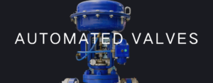
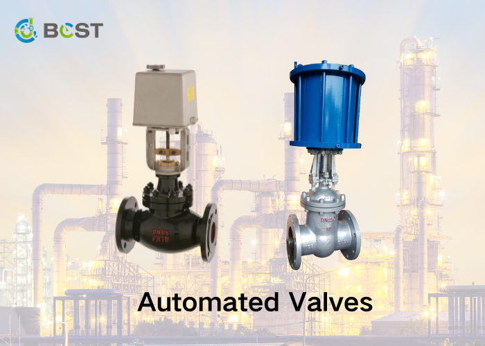
In the fast-paced world of industrial automation, innovation continually reshapes how we approach efficiency and precision. One such groundbreaking advancement that has transformed various sectors is the integration of automated valves. These sophisticated valves, driven by cutting-edge technology, have emerged as game-changers, streamlining processes, enhancing control, and elevating overall operational performance.
In this article, we’ll delve into the fascinating realm of how automated valves work and the functioning of automated gate, globe, and butterfly valves.
What are Automated Valves?
Automated valves are advanced control devices that leverage automated technology to regulate the flow of liquids, gases, or other substances within a system. Unlike traditional manual valves that require manual manipulation, automated valves are equipped with actuators, sensors, and controllers that operate automatically based on preset conditions or real-time feedback.
Automated valves find widespread use in industries such as oil and gas, water treatment, manufacturing, and more. Their automation capabilities enhance efficiency, reduce the need for manual intervention, and contribute to safer and more precise control of fluid systems. Automated valves are crucial in modern industrial processes, from simple on/off functions to complex proportional control.
How Automated Valves Work?
The goal of automating valves is to make them self-acting and responsive to process factors or specific working conditions. To do this, sensors detect changes in quantities such as pressure and temperature, and the control system sends a signal to the actuator, instructing it to take the necessary action. Although the basic principle of automated valves is the same, the functioning principle changes depending on the type of actuator used. Pneumatic, hydraulic, and electric actuators are all common types.
Pneumatic Actuators
These actuators are powered by air pressure, which ranges from 3 to 8 bar depending on the size and speed of the valve. The control unit distributes air to the diaphragm or piston linked to the stem to operate an automated valve. The air signal entering the valve is determined by a measurable variable, such as process temperature or pressure, and hence does not require human involvement.
The actuator is said to be directly acting when air pressure shuts, the valve spring action opens it, and the valve generally closes. If, on the other hand, air pressure opens the valve and spring action shuts it, the actuator is in reverse, and the valve is ordinarily open. There are also double-acting actuators, which allow air to enter from both sides of the diaphragm. As a result, the position of the valve is determined by the differential pressure across the diaphragm.
Hydraulic Actuators
Hydraulic actuators, like pneumatic actuators, use fluid pressure from oil or water to control valves. Also, a piston converts signal pressure into valve stem motion with a spring force, returning the valve to its normal position on pressure loss. They can handle high-force applications but cannot activate valves as quickly as pneumatic actuators. Generally, the fluid supply line to the valve is one inch or less to ensure speed and high pressure for controls. A solenoid activates to allow fluid to enter and control the valve.
Electric Actuators
Electric actuators typically use reversible, high-speed motors to open, close and regulate valves. They are more energy efficient, non-toxic, and quiet than pneumatic and hydraulic systems. Furthermore, the connection from the motor to the valve is often made through a gear system, which limits speed while increasing torque delivery to the stem. A reversible motor enables valve operation in both directions (open and close). Electric actuators are appropriate for big and high-pressure valves because to their quick reaction and strong torque.
Factors to Consider when Automating Valves
Automating valves involves careful consideration of various factors to ensure optimal performance, efficiency, and safety in industrial processes. The following are key factors that should be kept in mind:
Torque Rating
This is an essential consideration in valve automation since the torque rating of a valve affects actuator requirements. The actuator’s proper sizing ensures it can open or close the valve whenever needed. The torque rating of valves varies depending on the kind and size of the valve, with quarter-turn valves requiring the least.
The flow media pressure is another aspect that influences torque rating. Breakaway torque is an important metric when defining a valve torque rating because it is the greatest torque necessary to operate the valve. The rotational force necessary to open a valve from a fully closed position is called breakaway torque. It is more than the valve’s running torque, and valve manufacturers usually provide its value in terms of nominal pressure.
Safety Factor
After obtaining the torque rating, a safety factor must be applied. The torque rating provided by the valve supplier/manufacturer may include a safety factor. However, this should be explicitly mentioned rather than inferred. The flow media, frequency of operation, and kind of operation all influence the selection of an adequate safety factor.
Size of Actuator
Following determining torque needs, the next step is to pick an appropriate actuator. The larger the actuator size for pneumatic and hydraulic valves, the lower the pilot pressure. Whatever the size of the actuator, it must provide torque equal to or more than the torque rating of the valve, including the safety factor.
Manufacturers design valves with an ISO 5211 mounting pad interface for ease of automation. This standard assures that the interface between the valve and the actuator is the same for all equipment operating within the same torque range. It also helps to eliminate the usage of costly mounting kits, which take up space and add weight to the assembly. Following this standard, the valve stem and actuator shaft will likely match properly. However, in other circumstances, the actuator shaft is larger. Thus, a simple reduction sleeve is sufficient to mate them properly.
Application Requirements
Understand the specific needs of your application, including flow rates, pressure levels, and environmental conditions. Different applications may require different types of valves and automation methods.
Valve Type
Select the appropriate valve type for your application. Common types include ball valves, butterfly valves, globe valves, and more. The valve type should align with the desired control characteristics and fluid properties.
Actuation Method
Choose the right actuation method based on your application requirements. Options include electric, pneumatic, hydraulic, or manual actuation. Consider factors like response time, torque requirements, and power availability.
Control System Compatibility
Ensure compatibility with the existing or planned control system. Integration with Distributed Control Systems (DCS) or Programmable Logic Controllers (PLC) is crucial for seamless communication and coordination within the overall industrial automation infrastructure.
Maintenance Requirements
Evaluate the ease of maintenance and the frequency of required inspections. Choose valves with designs that facilitate accessibility and troubleshooting, minimizing downtime and maintenance costs.
Scalability and Future Expansion
Plan for future needs and expansion. Ensure that the automated valve system can scale to accommodate changes in production volume or modifications to the industrial process.
Cost-Benefit Analysis
Conduct a thorough cost-benefit analysis to justify the investment in automated valves. Consider factors such as energy efficiency, reduced labor costs, and the potential for increased productivity and reliability.
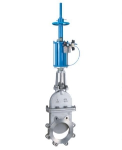
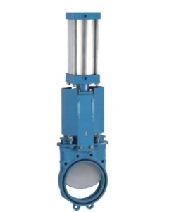
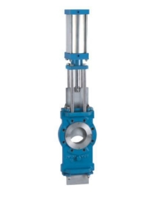
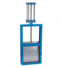
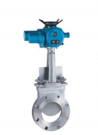
Automated Gate Valves
Automated gate valves are suited for shutdown applications in which the valve is either completely open or completely closed. This is due to the non-linear relationship between the vertical motion of the valve and the flow rate. The actuator must turn the stem multiple times to open or close a gate valve when it is automated. As a result, torque is an important factor to consider when automating gate valves. Gate valves are often mechanized utilizing pneumatic or electric actuation.
In the case of pneumatic actuation, a diaphragm is usually mounted in the cylinder to allow air pressure to enter from either or both sides. This cylinder typically sits at the top of the valve. The automated control system responds to a measured variable such as flow volume, temperature, pressure, and so on.
On reaching the threshold of the measured variable, the control system allows air pressure into the cylinder to move the diaphragm upwards or downwards. As the diaphragm is connected to the valve stem, it moves the valve disc to either close or open it. If the valve is to fail-open or fail-close, then actuation must be in only one direction, with a spring returning it to its fail-safe position on loss of pressure.
On the other hand, electric actuators utilize a motor to spin the stem to raise or lower the gate. To improve torque, this electric motor is connected to the stem via a gear system. Electric actuators are more suitable for fail-as-is designs and operate gate valves more quickly.
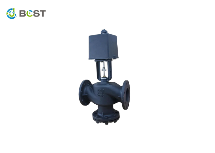
Automated Globe Valves
The automation of globe valves is similar to gate valves as they are both rising stem valves and require linear force to open and close. However, the torque requirement for globe valve actuators is less as the disc’s distance is less traveled. Pneumatic, hydraulic, and electric actuators can be used in automated globe valves.
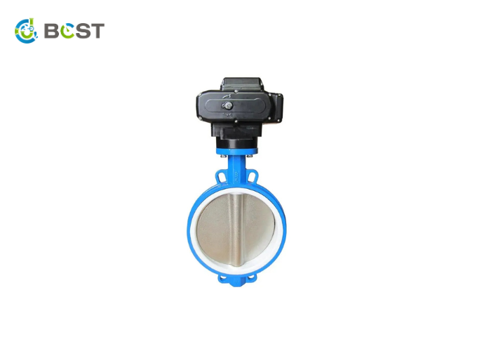
Automated Butterfly Valves
Of the three valves, butterfly valves offer the easiest route to automation because of their minimal torque requirement—the valve disc pivots at the middle of the pipe with an actuator rotating the disc. A parallel position to the pipe allows flow, and perpendicular to the pipe obstructs flow. As a result, butterfly valves are classified as “quarter turn” valves. They are ideal for large pipes with minimal debris and are effective in throttling applications.