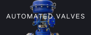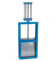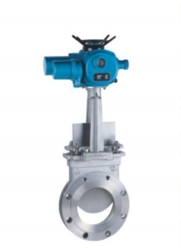
What is a Relief Valve?
Relief valves are an essential component in any hydraulic system. They allow for the safe operation of the system, but they can also come in handy when you need to shut down a process or equipment.
A relief valve is a safety device that allows pressure to build up inside the system before it reaches its breaking point and causes damage. A relief valve can be either a primary or backup relief valve, depending on what type of application you’re working with.
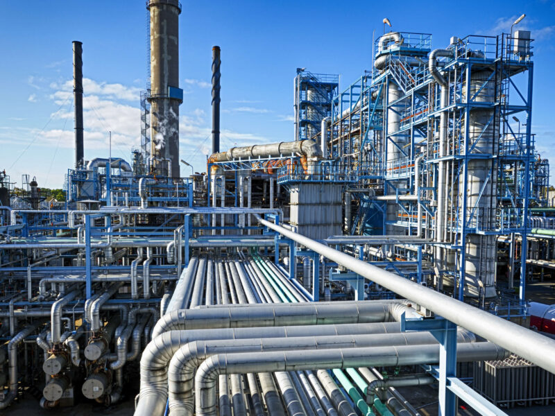
Main relief valves are used for high-pressure oil drilling or mining. If there’s too much pressure inside your system, your main relief valve will kick on and let off some of that pressure, so everything stays safe and working correctly.
Backup relief valves are helpful when you need additional protection against leaks in your system or if someone has accidentally left them open during operation. These valves should be set higher than your main relief valve so they can’t hurt anything if they fail during the process – which they will!
Failure Scenarios Common to Relief Valves
The most common failure scenario for relief valves is when a relief valve does not open due to debris in the hydraulic system.
In a mobile system, the control valves have pressure relief built-in to either the end stations or each operating station. This lets the machine designer customize the operation to the function rather than having one pressure set for all parts. In this example, we’re going to don’t forget a track-pushed excavator. There may be ten valves in a manifold, operating cylinders, and motor functions. Whereas the system pump can provide up a pressure of up to 5000 psi – but the relief valve confines it down to 3500 psi.
The tank operates the arm and the motor turns the swivel to keep the bucket in the right location. Engines also run the tracks which propel the device. If a seal in one of these cylinders tears up internally, it can send debris into their internal passage and cause them not to open up properly.
When this happens, you will also see that these systems supply no pressure – even though they operate correctly!
Damages & Downtime Costs
Damage to hydraulic equipment can be costly, damaging, and time-consuming. The cost of downtime is high due to the high cost of replacement parts and the need for human labor. It will take numerous hours to smooth up the hydraulic mess across the system and update the blown connection. Humans will take even longer to heal from any hydraulic failure injury.
The time frames for discovery and repair depend on how quickly a technician can access the machine after noticing it doesn’t work correctly. Still, it would take at least a day before techs discover the cause. The relief valve or cylinder seal might be replaced if damaged, but this may not be necessary unless there are other issues with pressure or flow in the system. However, if further investigation reveals an external problem (such as a leaky hose), then replacing it would likely be necessary so that everything can operate properly again.
In addition to cost and labor costs, additional expenses will be associated with replacing parts such as oil, hoses, and more! Some features may be relatively cheap, while others may cost more than $100 each, depending on their model number.
Identifying and Preventing Common Relief Valve Failures
When a relief valve fails, it can cause severe damage to your equipment and even cause injuries. Therefore, you need to install a secondary safety relief valve to prevent this from happening.
A secondary safety relief valve would have safeguarded this system, preferably partnered with a pressure sensor or over-pressure warning device. When the preliminary relief failed, the secondary relief would only allow the system to go slightly above the working pressure and not be high enough to fail components.
For example, the system may not reach 5000 psi, but only 3700 or 3800 psi. In this situation, the operator would likely notice a change in function efficiency from the equipment and notify management or maintenance of something wrong. Additional investigation by the maintenance department will fix these problems and the system will be repaired without any critical system failures, oil leaks or injuries.
All that is required to set up secondary comfort in a maximum system is to connect the pressure line to the relief valve and add a line from the relief valve, again reducing to the reservoir. You need to additionally upload a gauge; however, it is optional. A few hoses and fittings can store loads or heaps of dollars.
Choosing the Right Relief Valve
Relief valves come in many shapes and sizes, but they all have one thing in common: they’re designed to relieve pressure. They do this by a combination of either a spring or direct action.
The most common relief valve design is the ball/spring type, which has a ball that holds back a hole in its side by applying pressure from the inside. This pressure can be regulated by the spring inside; changing the amount of spring pressure will change the pressure that the ball can withstand.
Other designs use a direct-acting mechanism – such as a poppet valve – or spool with a pilot-operated mechanism to open and close a flow path which operates the mechanism of a secondary flow path.
This secondary flow path can have a high flow or require a precise operation, so direct-acting valves can also enjoy gadget surprises and soar as they are “directly” within the flow path. In contrast, pilot-operated valves act as buffers against these effects.
Our engineers and staff will work with you to accomplish the job from the initial concept design to the installation. Email us at [email protected] or go to our internet site at www.bcstgroup.com.
Selecting the Correct Relief Valve
Relief valves come in many shapes and sizes, but all of them have one thing in common: they’re designed to relieve pressure. They do this by a combination of either a spring or direct action.
The most common relief valve design is the ball/spring type, which has a ball that holds back a hole in its side by applying pressure from the inside. This pressure can be adjusted by adjusting the spring inside; varying the amount of spring pressure will vary the amount of pressure the ball will hold back.
Other designs use a direct-acting mechanism – such as a poppet valve – or spool with a pilot operated mechanism to open and close a flow path which operates the mechanism of a secondary flow path.
This secondary flow path can have a high flow or require a precise operation, so direct-acting valves may experience system shock and bounce as they are “directly” in the flow path, while pilot-operated valves act as buffers against these effects.