
Precision and control are critical in the field of industrial automation. Pneumatic Diaphragm Actuator, an engineering marvel crucial in regulating valves and controlling various industry processes. While it might sound like a complex piece of machinery, understanding how it works is not rocket science, and once you get the hang of it, you’ll be amazed by its simplicity and effectiveness.
In this blog, we will delve into the inner workings of the Pneumatic Diaphragm Actuator, demystifying its operation and shedding light on its essential role in the world of automation. Whether you’re a seasoned engineer or simply curious about the mechanics behind industrial automation, this article will provide a clear understanding of how this fascinating device operates. So, let’s roll up our sleeves and journey to uncover the secrets of the Pneumatic Diaphragm Actuator!
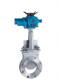
Pneumatic Diaphragm Actuator
When compared to electric, hydraulic, and manual actuators, the diaphragm actuator belongs to the pneumatic actuator class and is the most extensively utilized. Due to its simple design and reliability, this type of actuator is primarily used in the industrial sector (chemical and petrochemical industry) and power plants.
The mode of operation is briefly explained: externally supplied compressed air sets a diaphragm connected to the valve stem in motion. The exact position is determined by an electric positioner, which regulates the compressed air supply. The positioning force of a pneumatic actuator depends on the diaphragm area and the pressure value of the compressed air. The typical area ranges from roughly 80 cm2 to 2,800 cm2.
Structure of a Pneumatic Actuator with a Diaphragm
Diaphragm actuators are classified into three categories:
- Diaphragm actuator with columns
The column actuator consists of two housing chambers made of steel or stainless steel, a diaphragm plate, spring(s), an actuator rod, and a special diaphragm with a fabric insert. It is feasible to adjust this design for different valves by using a crosshead and columns.
- Diaphragm actuator with yoke (central connection)
Actuators with central connections do not have actuator columns installed. With a cast yoke, this actuator can be adapted to fittings.
- Diaphragm actuator with lever
Pneumatic lever actuators operate butterfly valves, ventilation dampers, and various control devices. A lever increases the limited stroke of a column actuator.
How does a Diaphragm Actuator work?
Pneumatic diaphragm actuators exploit the proportional relationship between control signal and actuator travel. The force operating on the diaphragm plate and spindle is converted from the air pressure on one side of the diaphragm. This force triggers the movement of the actuator spindle in one direction until the positioning force is balanced by one or more actuator springs. Because of the proportionate link between spring travel and restoring force, the control signal and actuator travel have a linear relationship.
These functionalities, combined with low friction (hysteresis) and high actuating forces, explain the popularity of this actuator type.
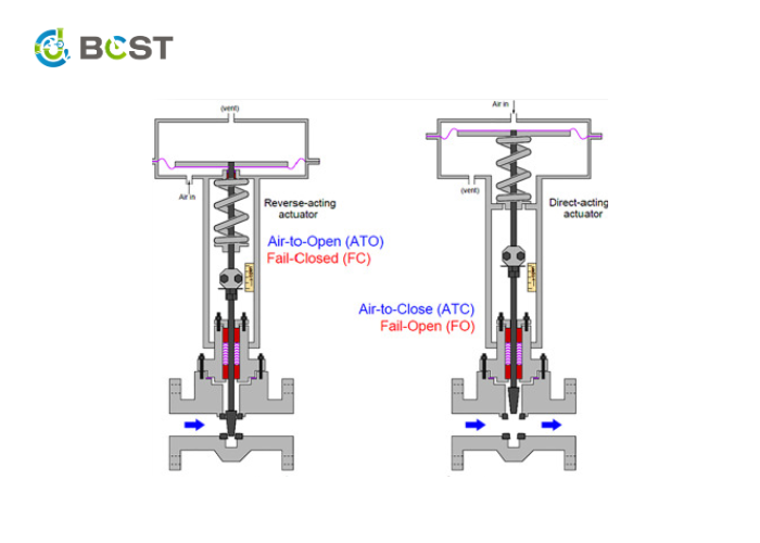
Pneumatic Actuator Operating Principles and Fail-Safe Position
Because of their unique safety function, diaphragm actuators play an important role in plant safety. The behavior in case of power failure is an essential criterion for selecting a pneumatic actuator. To move the process to a safe state in the event of a failure, it must already be determined whether the actuator should open or close the control valve during sizing.
If compressed air is no longer available, the spring return force pushes the control valve to its rest position – the fail-safe position. The diaphragm and springs can be arranged so the valve either closes or opens when the supply air fails.
Single-acting diaphragm actuators are available in two varieties. The mode of operation is determined by the installation position of the spring assembly and the pressure connection:
Direct acting:
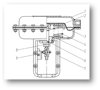
- Up diaphragm casting
- Diaphragm
- Diaphragm plate
- Spring
- Down diaphragm casting
- Actuator stem
- Yoke
- Adjust nut
- Travel indicator
- The air pushes the diaphragm down and closes the valve.
- Spring opens the valve.
- Fail-safe position: Valve open
Reverse acting:
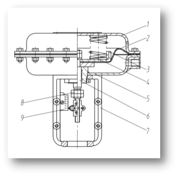
- Up diaphragm casting
- Diaphragm
- Diaphragm plate
- Spring
- Down diaphragm casting
- Actuator stem
- Yoke
- Adjust nut
- Travel indicator
- Rising air pressure opens the valve.
- Spring closes the valve.
- Fail-safe position: Valve closed