
Control valve & on off valve ,solenoid-valve manufacturer


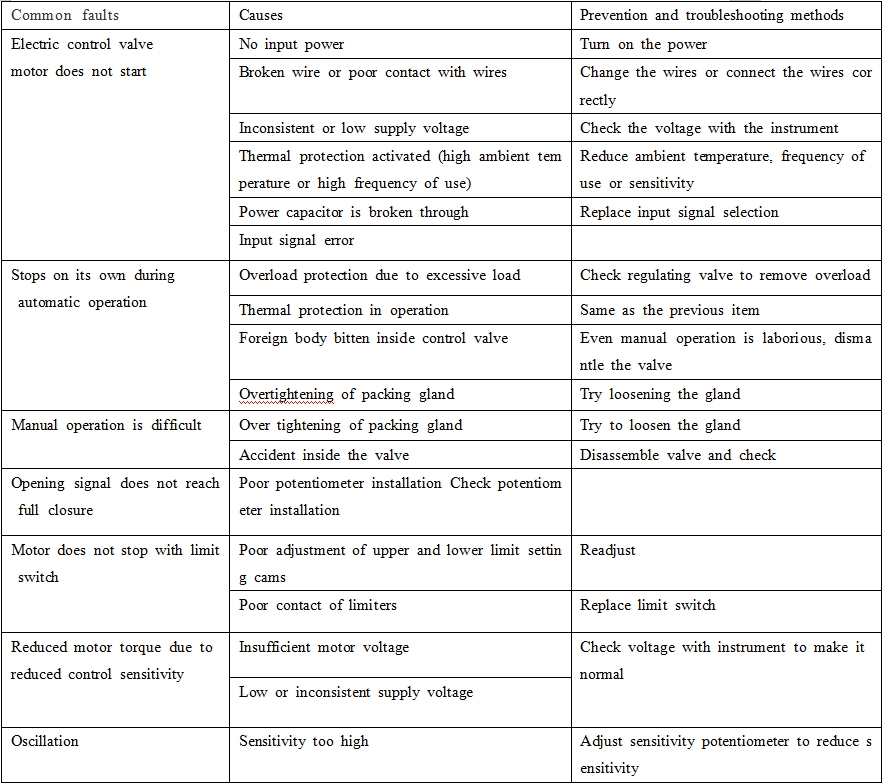
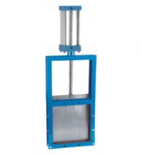
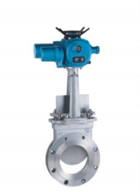
BCST your Expert Knife Gate Valve Supplier in China BCST Knife Gate Valve is widely used in urban
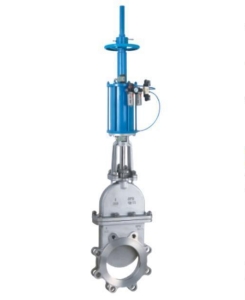
BCST your Expert Knife Gate Valve Supplier in China BCST Knife Gate Valve is widely used in urban
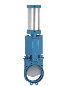
BCST your Expert Knife Gate Valve Supplier in China BCST Knife Gate Valve is widely used in urban
BCST your Expert Knife Gate Valve Supplier in China BCST Knife Gate Valve is widely used in urban
BCST your Expert Knife Gate Valve Supplier in China BCST Knife Gate Valve is widely used in urban