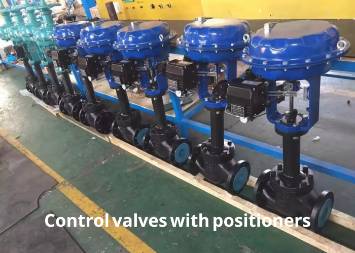
Pneumatic diaphragm control valves are widely used in chemical production. As an additional tool for the pneumatic film adjustment valve, the valve positioner plays a decisive role in using the adjustment valve. Therefore, the quality of the positioner adjustment directly affects the use of the regulating valve, which will affect the operation of the process.
With the development of the times, conventional positioners have been gradually replaced by intelligent positioners. Our smart positioners can be installed on different types of control valves. They have strong versatility, reasonable price, and high-cost performance. Therefore, they are designated as universal positioners by our factory.
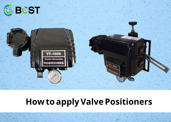
Control valves are commonly used in gas control systems, and positioners are the most common accessory for control valves. Many control systems have poor regulation quality, many of which are caused by the improper selection of positioners.
Pneumatic valve positioners have been in use since the 1920s. Many people have chosen positioners or relays for control valves for a long time based on some traditional empirical principles. They believe using a valve positioner is the best way to ensure that the spool position changes proportionally to the regulator output signal. As a result, valve positioners are widely used.
Despite the different shapes and forms of the various valve positioners and the differences in their operating principles, they all function similarly. For example, positioners for membrane actuators are usually mounted on the side, while piston actuators are usually mounted on the top. They all have a mechanical connection to the valve stem or piston (i.e., a feedback lever) to compare the position of the branch with the output signal from the regulator.
2.Analysis of the role of the positioner
The valve positioner and the regulating valve can be seen as a follower adjustment system for the valve stem position. It is equivalent to a secondary circuit (valve position secondary circuit) in the whole control system.
3. Calibration of the valve positioner
We set the switches via the local user interface DIP. It enables the positioner’s gain, positive and negative action to be performed. It also completes the basic settings for the positioner’s characteristics and whether an automatic adjustment is allowed. The valve positioner can be calibrated automatically or manually without additional tools. Manual control of the regulating valve can also be achieved using a manual control button in the local user interface.
4. Features of the valve positioner
4.1 Alarm functions
The ground panel has three red, yellow, and green light-emitting diodes, which we use in various combinations to indicate operating status or warning conditions. It has a diagnostic and monitoring function.
4.2 Air consumption of the valve positioner
The valve positioner consumes very little air, only 0.12 NM3/h at 0.6 MPa steady state, less than 8% of a conventional positioner. It is insensitive to changes in gas source pressure.
4.3 Travel role of the valve positioner
We use the same model for both straight and angular strokes. We optionally have a double-acting module that will enable the control of a double-acting piston-cylinder actuator.
4.4 Positioning pressure of the valve positioner
The “Tight Close” function sets the starting air pressure by default to ensure that the actuator has the correct positioning pressure on the valve seat. The regulating valve is “tightly closed” at zero position under different operating conditions.
4.5 Communication protocol of the valve positioner
The valve positioner uses the HART communication protocol, which communicates with the positioner in both directions.
5.Precautions for the use of the valve positioner
5.1 High requirements for the load-carrying capacity of the regulation signal
In actual use, the input impedance of the valve positioner is high. When the input signal is 20mA, the minimum required value of the power supply voltage is 12VDC, and the load-carrying capacity is not less than 600Ω. Otherwise, the positioner cannot work usually. Therefore, the minimum input current is not less than 3.6mA to ensure performance.
5.2 The dead action zone of the positioner should be set reasonably
The smaller the quiet area of the valve positioner is set, the higher the positioning accuracy, which creates a misunderstanding for people. It is thought that the smaller the quiet room, the better, but this will make the piezoelectric valve and feedback lever, and other moving parts move more frequently. Sometimes it will cause the valve to oscillate, affecting the life of the positioner and the valve. Therefore, it is not easy to set the deadband of the positioner too small. When the positioner setting is changed, we must re-tune it before it can take effect.
6.Installation of the valve positioner
An essential principle in installing the positioner is that the positioner, stem, and feedback lever form closed-loop negative feedback.
We can check this way: after the positioner is installed, the valve stem and the feedback lever are not connected, and the feedback lever is turned by hand. If the direction of action of the valve stem is opposite to the direction of movement of the feedback lever, it means that closed-loop negative feedback has been constituted. Therefore, we have to adjust the valve position to 50% and put the feedback lever in the horizontal position. Then the feedback lever and the valve stem will be fixed, which will ensure that the positioner works in the best linear section. If the positioner is not installed squarely, it will also increase its linear deviation.
7.Selection of the flow characteristics of the valve positioner
The processing characteristics of the spool determine the flow characteristics of the control valve. If the process requirements match them, the output characteristics of the positioner should be selected as linear output.
In practice, if the spool characteristics do not match the process requirements, the overall flow characteristics of the valve can be changed by setting the output characteristics of the positioner. For example, suppose the spool is a linear control valve. We can change the valve with a linear spool into a valve with equal percentage flow characteristics by setting the positioner output characteristics to similar percentage characteristics.
8.Repair of valve positioners
The different functional modules of the valve positioner are damaged, which will cause the positioner to be unusable. If the whole is replaced, the cost is high. In this case, the positioner can be reassembled using the non-faulty module, but it has to be reset according to the different regulating valves after assembly.
As the regulating valve (stroke etc.) using the positioner has changed, we may not be able to achieve the required use using automatic adjustment. At this point, we can first manually adjust it to determine its stroke and then calibrate it with the automatic adjustment. It allows the regulating valve to be positioned accurately and with the correct response speed to meet the process control requirements and saves a lot of money.
9.Conclusion
The control valve is the terminal of the control system. Once a failure occurs, it will directly affect the safe operation of the device and significantly impact the production process. Intelligent valve positioner, its performance has been dramatically improved due to the use of microprocessors and new components. As a result, it is more widely applicable, easier to use, and more reliable, laying the foundation for a safe, stable, long, complete, and excellent production.