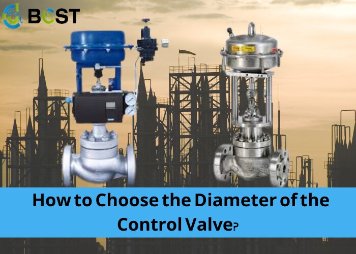
Calculation of regulating valve caliber needs to determine the calculated flow rate, determine the calculated differential pressure, calculate the flow capacity, select the flow capacity, check, and determine the regulating valve caliber of the six steps, today to share with you the knowledge related to the selection of regulating valve caliber.
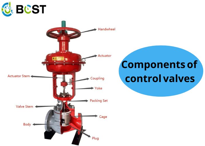
Flow capacity is the main basis for selecting the caliber of the control valve. In order to correctly calculate the circulation capacity, the first no must be reasonable to determine the flow rate of the control valve and the value of the differential pressure. Usually, the flow rate and differential pressure in the flow capacity calculation formula are called calculated flow rate and calculated differential pressure.
Ⅰ. Calculated flow rate determination
Calculated flow refers to the maximum flow through the control valve. Flow value should be based on the production capacity of the process equipment, the object load changes, changes in operating conditions, and the quality of control of the system and other factors for comprehensive consideration and reasonable determination. However, there are two tendencies that should be avoided: one is too much consideration of the margin, so that the valve caliber selected too large, which not only causes economic waste, but also will make the valve often in a small opening work, so that the controllable ratio is reduced, the control performance deteriorated, and in serious cases, even caused by vibration, which greatly reduces the life of the regulating valve; the second is to consider only the immediate production, one-sided emphasis on the control of the quality, so that when the productivity of the slight increase in the Control valve can not adapt, forced to replace.
Calculate the flow rate can also refer to the capacity of pumps compressors and other fluid transfer machinery to determine. Sometimes, a combination of methods to determine.
Ⅱ. Calculated differential pressure determination
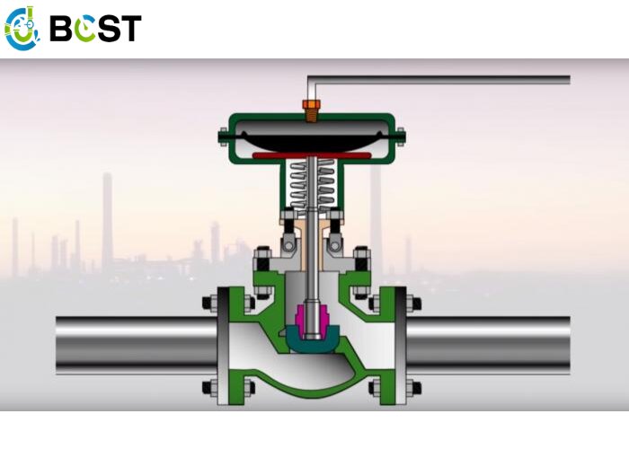
Calculated differential pressure refers to the control valve valve being fully open, and the flow rate of the maximum pressure difference on the control valve. Determine the calculated differential pressure must take into account both control performance and power consumption. Differential pressure on the valve accounted for the ratio of the whole system differential pressure is greater, the smaller the distortion of the flow characteristics of the control valve, the more control performance can be guaranteed. However, the larger the pressure difference before and after the valve, the more power consumption.
Calculate the differential pressure is mainly based on the process piping, equipment, and other components of the system differential pressure size and changes in the selection, the steps are as follows:
① The closest distance before and after the regulating valve, the pressure is basically stable two devices as the calculation range of the system.
② in the maximum flow conditions, respectively, the system calculates the local resistance (except the control valve) caused by the pressure loss △ PF and then finds the sum of their Σ△ PF.
③ Select the value of S. The value of S should be the full opening of the control valve on the differential pressure △ PV and the total pressure loss of the system ratio, that is, S = △ PV ÷ (△ PV + Σ △ PF), often selected S = 0.3-0.5. But some systems, even if the value of S is less than 0.3 can still meet the requirements of the control performance. For high-pressure systems, in order to reduce power consumption, can also be reduced to S = 0.15. For gas media, because the resistance loss is small, the differential pressure on the regulating valve accounted for a larger component, so the general value of S value is greater than 0.5. But in the low-pressure and vacuum systems, due to the allowable pressure loss being small, the S is still 0.3-0.5 is appropriate.
④ According to the calculated Σ△PF and selected S value, using the formula S = △PV ÷ (△PV + Σ△PF) can be calculated by the regulator valve differential pressure △PV = S Σ△PF ÷ (1 – S).
Taking into account that the system equipment in the static pressure often fluctuates, will affect the change of differential pressure on the valve so that the value of S further declines. Such as boiler feed water control system, the calculated differential pressure should increase the static pressure of the system equipment (set the boiler rated static pressure of P) of 5% -10%, that is, △PV = SΣ△PF ÷ (1-S) + 0.0521P.
The increase in differential pressure on the control valve is certainly beneficial to the control, but too large a differential pressure may make the control valve cavitation phenomenon. The presence of cavitation should also be considered when determining the calculated differential pressure.
Ⅲ.Calculation of control valve adjustment opening and controllable ratio
Calculation of the flow rate and calculation of differential pressure to determine the regulating valve should be made after the opening and controllable ratio of the calculation.
①Calculation of valve opening
The general maximum flow rate of the valve opening should be about 90%, and the minimum flow rate of the valve opening not less than 10%. The opening of the calculation must take into account the ideal flow characteristics of the valve and operating conditions. Given below are two commonly used flow characteristics of the control valve in the working conditions (series piping) of the opening calculation formula.
Linear characteristics of the regulating valve opening:
Equal percentage control valve opening:
Where k is the flow qi at the valve opening; qi is the flow rate at the check opening, m3 / h; r for the medium density, kg / m3.
② Controllable ratio of the check
At present, in China’s unified design of the control valve, the ideal controllable ratio R is generally 30, but in use by the maximum opening and minimum opening limitations, generally make the controllable ratio down to about 10. In the case of series piping, the actual controllable ratio Rc = R √ S. Therefore, according to the following formula Rc = 10 √ S for the controllable ratio of the check, if Rc> max/min, then the selected control valve meets the requirements. Otherwise, you must change the S value of the control valve, which can be taken to increase the system pressure or the use of two control valves (reduce the S value), to meet the requirements of the control ratio of the method of split-range control.
In summary, according to the data provided by the process to determine the caliber of the regulating valve steps are:
① Determine the calculated flow: according to the production capacity, equipment load, and media conditions, determine the calculated flow qmax and qmin.
② determine the calculated differential pressure: according to the selected flow characteristics and system characteristics of the selected S value, and then decide to calculate the differential pressure.
③ Calculate the circulation capacity: According to the calculated flow rate and calculated differential pressure that have been decided, find the circulation capacity C max at the maximum flow rate.
④Select the flow capacity C: According to the C max obtained, select the C value that is larger than C max and closest to it in the standard series of the selected product type.
⑤ Calculation: Calculate the control valve opening and controllable ratio.
⑥ Determine the caliber of the control valve: after passing the test, according to the flow capacity of the C value determine the nominal diameter of the control valve and valve seat diameter.