In the automatic control of modern plants, control valves are critical. They accept control signals from the control unit and thus change process parameters such as medium flow, pressure, temperature, and level. Control valves are the last gate in the process loop! Therefore, how to choose the correct control valve to achieve the best control effect? It becomes a most critical issue.
The selection of control valves should be based on the features of the control system, the source of disturbance, and the S (valve resistance ratio) value.
1.Inherent flow features of control valves
1.1 General selection
1.1.1 The differential pressure on the valve becomes smaller, the given value becomes smaller. Therefore, the primary variable of the process also becomes smaller, and S > 0.75 control objects, we should choose linear flow characteristics.
1.1.2 Slow production process, when S > 0.4, we should choose linear flow characteristics.
1.1.3 It requires an extensive adjustable range, the pipeline system pressure loss, opening changes, and differential pressure changes on the valve relatively large occasions, we should choose equal percentage flow characteristics.
1.1.4 For fast production processes, when we do not know much about the dynamic process of the system, we should choose the equal percentage flow feature.
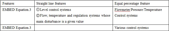
1.1.5 According to previous experience, it can also be selected according to the following table flow features.
Note: △Pn:Indicates the differential pressure at both ends of the valve at normal flow.
△PQun1 – indicates the differential pressure at both ends of the valve with the valve closed
1.1.6 quick-opening characteristic: it is suitable for applications with two-position action. It is also ideal for situations where the maximum flow capacity of the regulating valve is obtained quickly. In addition, when the regulator has to be set in a wide proportional band, the fast-opening characteristic can also be used for the regulating valve.
1.2 Valve type selection
1.2.1 Process variables
Temperature, pressure, pressure drop and flow rate, etc.
1.2.2 Fluid features
Viscosity, corrosiveness, toxicity, presence of suspended matter or fibres, etc.
1.2.3 The requirements of the regulating system
Adjustable ratio, leakage, noise, etc. The regulating valve pipeline connection form to choose a comprehensive regulating valve type.
1.2.4 In general, we prioritize small size, sizeable passing capacity, advanced technology, straight-through single and double-seated control valves, and standard sleeve valves. You can also choose low S value energy-saving valves and small regulating valves.
1.2.5 We can use the following control valves according to different occasions.
① The application of the control valves
It is generally applicable to the process requirements of small leakage, small flow, the valve before and after the pressure difference is small occasions. However, if its bore is less than 20mm, it can also be widely used for more significant differential pressure occasions. Similarly, it is also suitable for high viscosity or containing suspended particles in fluid events.
②Through double-seat valve
It is generally applicable to the leakage requirements are not strict, the flow rate is significant, and the pressure difference between the front and rear of the valve is important occasions. However, it is unsuitable for high viscosity or fluid containing suspended particles.
③Sleeve valve
It is generally suitable for applications where the fluid is clean and does not contain solid particles. It has a significant pressure differential between the front and rear of the valve and where the fluid may flash or cavitate.
It is suitable for high viscosity, containing fibers granular and foul fluids.
The adjustment system requires a wide range of adjustable (R up to 200:1; 300:1) occasions.
When the valve seat gasket is made of soft material, it requires a tight seal.
The “O” type ball valve is generally applicable to the occasion of a two-position cut-off.
“V” type ball valve is generally applicable to continuous adjustment systems. Its flow characteristics approximate to equal percentage.
⑤Angle type valve
It is generally suitable for the following applications.
High viscosity or suspended fluids (if necessary, can be connected to the flushing liquid pipe).
Fluids in mixed gas-liquid phase or prone to flash vapour.
Pipelines require right-angle piping occasions.
⑥High pressure angle type valve
It is suitable for high static pressure significant differential pressure occasions. However, the material and structure of the inner parts of the valve must be reasonably selected to extend the service life.
⑦Body separation type control valve
It is suitable for high viscosity, containing particles, crystals, and fiber fluid. When it is used for strong acid, strong alkali, or robust corrosive fluid occasions, the valve body should be selected with corrosion-resistant lining, valve cover, spool, and valve seat should be used corrosion-resistant pressure pad or the corresponding corrosion-resistant materials. Its flow characteristics are better than diaphragm valves.
⑧Eccentric rotary valve
It is suitable for large flow capacity, adjustable ratio wide (R up to 50:1 or 100:1), and considerable differential pressure, tight seal occasions.
It is suitable for large bore, large flow, and low-pressure differential occasions.
It is also suitable for thick turbid fluid and fluid containing suspended particles.
It requires tight sealing occasions. We should use a rubber or PTFE soft sealing structure; the corresponding corrosion-resistant lining needs to be used for corrosive fluids.
⑩Three-way valve
It is suitable for diversion and merging where the fluid temperature is below 300°C. It is also used for simple proportional adjustment. The temperature difference between the two fluids should not be more significant than 150℃.
⑪ The application of the valves
It is suitable for solid corrosion, high viscosity. It is also ideal for fluids containing suspended particles as well as fibers. Also, for occasions where flow characteristics are not strictly required. However, due to the limitations of the diaphragm lining, we can only use it for applications where the pressure is less than or equal to 1MPa and the working temperature is less than 150°C.
⑫Bellows seal valve
It is suitable for highly toxic, volatile, rare, and valuable liquids for vacuum systems and fluids.
⑬Low temperature control valve
It is suitable for low-temperature working conditions and profound freezing occasions.
It’s the medium temperature at -100 ~ 40 ℃. We can choose the heat sink (here for heat absorption) plus a flexible graphite packing valve. If the medium temperature is at -200 ~ -100℃, we should choose the long neck type low-temperature valve.
⑭Low S-value energy-saving regulating valve
It is suitable for process load changes or when the S value is less than 0.3.
⑮Low noise valve
It is suitable for liquid flashing, cavitation, and gas flowing at the valve shrinkage surface at a speed more significant than the speed of sound and the predicted noise exceeds 95dB (A).
⑯Fast shut-off valve
It is suitable for a two-position regulating system and process failure. We need the valve emergency open or close the occasion.
⑰Self-operated regulating valve
It is suitable for small changes in flow, and regulation accuracy requirements are not high or instrumentation gas supply difficulties occasionally.
In the unique production process, we should choose a special regulating valve according to experience.
2.Control valve materials
2.1 General selection
2.1.1 The pressure rating, temperature range and corrosion resistance of the valve body and materials shall not be less than that required for the process connection piping materials. We should give priority to the manufacturer’s final product. The general situation choose cast steel or forged steel valve body.
2.1.2 Water steam or wet gas containing more water and flammable fluid should not choose cast iron valve body.
2.1.3 The ambient temperature below -20 ℃ should not be selected cast iron valve body.
2.1.4 Valve parts should resist corrosion, fluid erosion, and fluid by throttling cavitation flash damage to the valve parts cavitation.
2.2 Valve inner parts material selection
2.2.1 Non-corrosive fluids generally choose 1Crl8Ni9, 1Crl8Ni9Ti, or other stainless steel.
2.2.2 Corrosive fluids should be based on the type of fluid, concentration, temperature, and pressure of the different fluid and fluid containing oxidants the flow rate of the other choice of suitable corrosion-resistant materials.
We often use corrosion-resistant materials such as 1Crl8Ni9Ti, 0Crl8Nil2M02Ti, 20# alloy, Hastelloy, and titanium steel.
2.2.3 For the significant flow rate, scouring severe conditions should be selected for wear-resistant materials. Such heat-treated 9Crl8 and 17-7PH, tight oxide layer, tough and fatigue strength of chromium-molybdenum steel, G6X, and other materials.
2.2.4 Material selection for severe wear occasions
When there is flash, cavitation, and fluid-containing particles, the surface of the spool and seat should be hardened.
When the fluid temperature is too high, and the pressure difference is too significant, the spool valve seat should be surface hardening treatment—for example, the surface of the welded stearic alloy.
3.Control valve leakage and flow
According to the requirements of the process on the amount of leakage to choose different levels of leakage of the valve type.The leakage of a general straight-through single-seat valve should be less than or equal to 0.01% of the rated C value, and the leakage of a double-seat valve should be less than or equal to 0.1% of the rated C value.
3.1 Selection of flow direction
3.1.1 Ball valves and standard butterfly valves have no requirement for flow direction and can be selected in any flow direction.
3.1.2 Three-way valves, venturi angle valves, double-sealed sleeve valves with balancing holes have been specified in a specific flow direction generally can not be changed.
3.1.3 Single-seated valves, angle valves, high-pressure valves, single-sealed sleeve valves without balance holes, small flow control valves, etc., should be based on different working conditions to choose the flow direction of the control valve.
①For DN ≤ 20 high-pressure valve, due to high static pressure, pressure difference, cavitation erosion is significant, we should choose to use the flow closed type; when DN > 20, we should choose the stability of good conditions to determine the flow.
②Angle-type valve for high viscosity, solid particles containing media requirements “self-cleaning” performance, we should choose to use the flow closed type.
③Single-seated valves, small flow rate control valves are generally used to open the flow type; when severe scouring, we can choose to close the flow type.
④Single-sealed sleeve valve is generally used to open the flow type; when there is a “self-cleaning” requirement, we can choose to close the flow type.
⑤Two-position control valve (single-seat valve, angle valve, sleeve valve, fast-opening flow characteristics), we should choose to use the flow closed type; when there is a water strike wheezing, we should switch to the flow open type.
⑥When we choose the flow-closed type and ds < d (ds – stem diameter; d – seat diameter), the valve has poor stability, we should pay attention to the following points.
Minimum working opening more significant than 20% to 30% or more.
The selection of springs with high stiffness.
Selection of equal percentage flow characteristics
4.Selection of control valve accessories
4.1 Valve positioners for applications
4.1.1. valve positioner can overcome friction. It can also improve the speed of regulating valve action occasions.
4.1.2. For split-range control and control valves that need to change the form of air opening and air closing.
4.1.3. Where the valve positioner needs to change the flow characteristics of the regulation.
4.1.4. The regulator proportional band is vast but requires the valve to respond to small signal occasions.
4.1.5. Occasions where a springless or piston actuator is required to achieve proportional action.
4.1.6. We use a standard signal and operate a non-standard spring actuator (spring range other than 20 to 100 kPa).
5. Installation of control valves
5.1 Basic requirements
5.1.1. The control valve should install vertically and upright on the horizontal pipeline. Nominal diameter DN ≥ 80mm control valve, its valve before and after the channel should be equipped with permanent support.
5.1.2 When we install a control valve, it needs to be positioned to be easy to operate and maintain. If necessary, we should set up a platform.
5.1.3 Control valve sets should have a compact piping combination to facilitate operation, maintenance, and drainage.
5.1.4 The upper and lower parts of the control valve should leave enough space for the actuator and valve internals to be removed during maintenance and the lower flange and plug of the valve.
5.1.5 Control valve for high viscosity, easy to crystallize, easy to vaporize, and low-temperature fluid should take insulation and anti-freezing measures.
5.1.6 The environment temperature of the control valve is generally not higher than 60℃ and not lower than -40℃.
5.1.7. When the valve is installed on a vibration occasion, we should consider anti-vibration measures.
5.1.8 The valve positioner is not installed in the regulating valve. We have to install a small pressure gauge on the diaphragm head to indicate the control signal.
5.1.9 Control valve containing suspended matter and high viscosity fluid should be equipped with a flushing pipeline.
5.1.10. When we install the control valve, we should pay attention to making the medium flow through the direction of the arrow as marked on the valve body.
5.1.11. Control valves should be checked and calibrated first and installed after pipeline purging.
5.2 Control valve bypasses
5.2.1 Bypasses should be provided for the following.
① Corrosive fluids.
② Where there is severe wear on the valve internals.
③ Other essential applications, such as boiler feedwater regulating valves.
5.2.2 Bypasses may not be provided in the following cases.
① Clean fluids.
② Nominal diameter DN>80mm.
③ When the control valve is faulty or overhauled. The process does not allow or cannot be operated using the bypass valve. For example, emergency interlock venting valve and slurry, easy to crystallize fluid, etc.
5.2.3 Control valve connection form should be in line with the manufacturer’s product description with the provisions of the book.
5.2.4. Control valve expands (shrink) tube, concentric and eccentric gradually expand (shrink) line, we should choose abnormal slowly develop (shrink) tube.