We need to determine the flow rate, differential pressure, and flow capacity when calculating the regulating valve diameter. At the same time, we also need to select the valve’s flow capacity, check the calculation, and the control valve bore. Today, we share the knowledge about the selection of control valves took
1. Control valve caliber selection
1.1 Calculated flow rate determination
The calculated flow rate is the maximum flow rate through the control valve. Flow rate value should be based on the production capacity of the process equipment, object load changes, changes in operating conditions and the system’s control quality, other factors to consider, and then reasonable provisions.
1.1.1 Notes on calculating flow rates
First, we take too much into account the margin, so that the valve caliber is selected too large, which not only causes economic waste. It will often make the valve in the small open degree work so that the controllable ratio is reduced and the control performance becomes terrible. In severe cases, it will cause oscillation, which significantly reduces the life of the regulating valve.
Secondly, we only consider the immediate production, one-sided emphasis on control quality. So that when productivity increases slightly, the control valve cannot adapt and is forced to be replaced.
Calculated flow rates can also be determined by reference to the capacity of fluid transfer machineries such as pumps and compressors. Sometimes, a combination of methods is used to determine this.
1.2 Flow capacity
The flow capacity is the primary basis for selecting the diameter of the regulating valve. To correctly calculate the flow capacity, the flow rate and differential pressure of the regulating valve must be determined reasonably. Therefore, we usually refer to the flow rate and differential pressure as the calculated and differential pressure when substituted into the flow capacity calculation formula.
1.3 Calculation of differential pressure determination
The calculated differential pressure is the whole opening of the valve of the regulating valve. Therefore, the regulating valve will have a differential pressure when the flow rate is maximum.
When we determine the calculated differential pressure, we must consider both the control performance and power consumption. The greater the differential pressure ratio across the valve to the differential pressure across the system. The smaller the distortion of the flow characteristics of the control valve, the more control performance can be guaranteed. However, the greater the pressure difference between the front and rear of the valve, the more power is consumed.
1.4 Steps for calculating differential pressure
Calculation of differential pressure is mainly based on the process piping, equipment, and other components of the system pressure difference size and changes. The steps are as follows.
1.4.1 We put the regulating valve before and after the closest distance, the pressure of the primary stability of the two devices as a system of calculation range.
1.4.2 Under the condition of maximum flow rate, calculate the pressure loss △PF caused by each local resistance in the system (except the regulating valve) and then find out their sum Σ△PF
1.4.3 We choose the S value. S value should be the regulating valve fully open, the control valve on the differential pressure △ PV, and the total system pressure loss ratio, S = △ PV ÷ (△ PV + Σ △ PF). We usually choose S = 0.3 – 0.5.
However, even when the S value is less than 0.3, the control performance requirements can still be met for some systems. For high-pressure systems, power consumption can also be reduced to S = 0.15. The pressure difference on the regulating valve accounted for a more significant component for gas media because the resistance loss is more minor. Therefore, the general value of S is more important than 0.5. However, in low-pressure and vacuum systems, S is still appropriate at 0.3-0.5 because of the minor permissible pressure loss.
1.4.4 We have worked out the Σ△PF and selected the S value. Using the formula S = △PV ÷ (△PV + Σ△PF) can be obtained from the regulating valve to calculate the differential pressure △PV = S Σ△PF ÷ (1 – S).
1.5 Influence of other factors on the calculation
We consider that the static pressure in the system equipment often fluctuates. It will affect the change of differential pressure on the valve so that the S value further decreases.
As in the boiler feedwater control system, the calculated differential pressure should be increased by 5%-10% of the static pressure of the system equipment (set the boiler rated static pressure as P), i.e., ΔPV=SΣΔPF÷(1-S)+0.0521P.
The increase in differential pressure on the control valve is undoubtedly beneficial to control, but too enormous a differential pressure may cause cavitation of the control valve. Therefore, we should also consider not producing cavitation when determining the calculated differential pressure.
2.Adjustment valve opening and control ratio of the test calculation
After the calculated flow rate and differential pressure are determined, we should calculate the regulating valve opening and the controllable ratio.
2.1 The opening of the regulating valve
The available maximum flow rate of the regulating valve opening should be about 90%, and the minimum flow rate of the regulating valve opening is not less than 10%. Therefore, when the opening degree is calculated, we must consider the ideal flow characteristics of the regulating valve and working conditions. In the following, we will give two common flow characteristics of the regulating valve in the opening verification formula’s operating conditions (series piping).
In-line characteristic adjustment valve opening
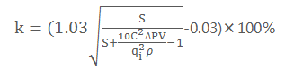
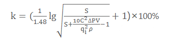
Where k is the valve opening at flow qi, qi is the flow rate at the verified opening: m3/h.
2.2 The control ratio of the calculation
In China’s unified design of control valves, the ideal controllable ratio R is generally 30. Still, in use, the valve by the maximum opening and minimum opening restrictions, we will generally make the controllable ratio down to about 10.
In the case of series piping, the actual controllable ratio Rc = R√S. Therefore, according to the following formula Rc = 10√S for controllable ratio calculation, if Rc > max/min, the selected control valve meets the requirements. Otherwise, we must change the S value of the regulating valve. We can also increase the system pressure or use two control valves (to reduce the value of S), the split control method to meet the controllable ratio requirements.
3.Conclusion
To sum up, the steps to determine the regulating valve diameter according to the data provided by the process are
3.1 Determine the calculated flow rate
The production capacity, equipment load, and media conditions determine the calculated flow rate max and min.
3.2 Determine the calculated differential pressure
The selected flow and system characteristics set S values and then determine the calculated differential pressure.
3.3 Calculate the flow capacity
Find the maximum flow rate when the flow capacity is Cmax according to the decided calculated flow rate and differential pressure.
3.4 Choose the flow capacity C
The Cmax has been obtained in the standard series of the selected product type, selected greater than Cmax and closest to the value of block C.
3.5 Calculation
Calculation of the control valve opening and controllable ratio.
3.6 Determine the diameter of the control valve
After passing the test, according to the flow capacity, the C value determines the control valve’s nominal diameter and seat diameter.