One option is a current regulated drive, which helps improve performance while significantly reducing energy consumption.
Solenoids are used in many applications to provide linear or rotary actuation in mechanical systems. While driving solenoids can be as simple as turning the current on and off, better performance is often obtained by driving them with a dedicated IC.
This paper will look at how drive circuits affect the electromechanical performance of solenoid valves. Two different drive circuits will be compared: a simple switch and a current-regulated driver. Energy-saving techniques to limit the power consumption of solenoids will also be covered.
In its simplest form, a solenoid is a coil that generates a magnetic field. The devices we commonly call solenoids are devices that use a coil and a moving core made of iron or sometimes another magnetic material. Applying an electric current to the coil causes the core to be pulled or pushed relative to the coil, resulting in motion used to drive objects in a mechanical system.
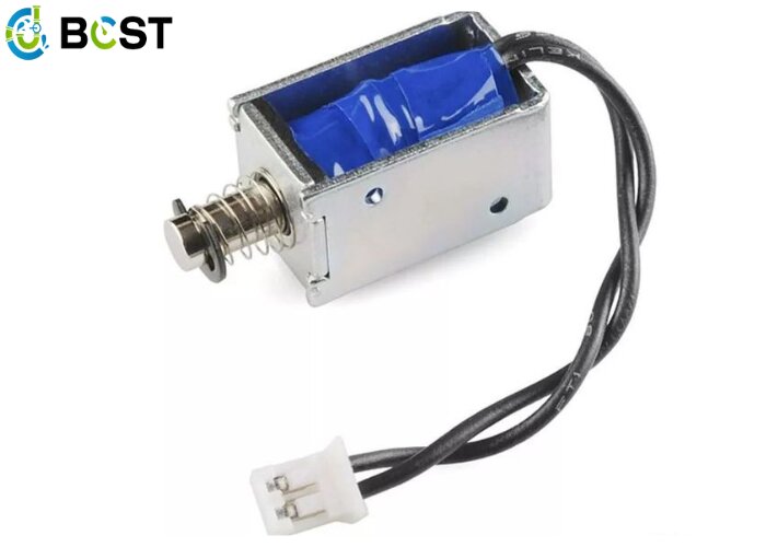
- A typical solenoid consists of a coil that produces a magnetic field.
When the solenoid is activated, a voltage is applied to the windings to create a magnetic field. Since the windings have a large inductance, it takes some time for a current to develop. The force on the solenoid core is proportional to the current. To generate the maximum force to move the core, a high voltage must be applied to the windings to build current quickly.
Once the movement is complete, a much smaller current can usually be used to hold the core in place. If the current is not reduced, considerable power is dissipated in the windings and the solenoid generates a lot of heat.
To solve these problems, we can use a constant current driver to drive the solenoid. We can control the current over time, to provide the desired action, and limit the power consumed by keeping the solenoid in place.
II Test Setup
To compare the electromechanical performance of different solenoid drive solutions, a simple test setup was constructed using a servo potentiometer connected to a solenoid with a flexure to measure the motion of the solenoid. The motion, along with voltages and currents, was captured using an oscilloscope.
2. The test setup involves a servo potentiometer connected to a solenoid with a flexure.
III Simple Solenoid Driver
The simplest way to drive a solenoid valve is to turn the current on and off. This is usually accomplished with a low-side MOSFET switch and a current recirculation diode. The current is only limited by the supply voltage and Solenoid DC Resistance in this circuit.
3. Driving the solenoid most simply is a matter of switching current, which is usually accomplished with a low-end MOSFET switch and current recirculation diode.
The electromechanical performance of a simple driver is limited. Since the full voltage and current are applied 100% of the time, the pull-in current is limited by the solenoid’s continuous power consumption rating. The large inductance of the coil also limits the rate at which the current increases when the solenoid is first started.
In our tests, the motion, voltage, and current of the solenoid were measured using a simple switch. In this case, the solenoid (15 Ω, rated at 12 V) took 30 ms to actuate and consumed 10 W of power whenever the solenoid was activated.

- These waveforms represent the motion of the solenoid with simple switches for voltage and current.
If you are wondering about the “valleys” in the current waveforms, the decrease in current is due to the counter-electromotive force generated by the moving core of the solenoid. As the core accelerates, the counter electromotive force increases until the bottom of the solenoid appears and stops moving.
IV High-Performance Solenoid Drivers
In most applications, full current is required only initially to pull in the solenoid. Once the movement is complete, the current level in the solenoid can be reduced, which saves energy and reduces the amount of heat generated in the coil. This also allows a higher supply voltage to be used, which provides a higher suction current, which allows the solenoid to start faster and provide more force.
- Shows the MPQ6610 reduced holding current circuit.
An MPS MPQ6610 half-bridge driver and a few external components accomplish this task. The MPQ6610 is rated up to 60 V and 3 A and is available in small TSOT and SOIC packages.
The resulting drive waveform is shown in Figure 6. The yellow trace is the output signal of the driving solenoid, and the green trace is the solenoid. Initially, the full supply voltage (24 V in this case) is driven to draw in the solenoid. After a delay, the current is reduced by pulse width modulation of the output. The introduction time is reduced to 16 milliseconds, keeping the power consumption much lower (about 600 milliwatts instead of 10 watts).

- These are the reduced current waveforms relating to the MPQ6610.
This circuit works like this:
Initially, the input signal is low. This discharges C1 through D1 and holds the ISET pin low through Q1.
The input signal goes high, which allows the MPQ6610 to drive the output high and apply the full supply voltage to the solenoid.C1 begins to charge through R1. The current comes from the ISET pin and is proportional to the current flowing in the solenoid. The voltage on the ISET pin is allowed to rise as C1 charges.
Assuming sufficient current is flowing in the solenoid, the voltage on the ISET pin continues to rise until it reaches its current regulation threshold (1.5 V). At this point, the MPQ6610 begins to regulate the solenoid current. The regulated holding current is set by the value of R2.
The delay time (driving the solenoid at 100% duty cycle) is set by the values of R1 and C1. For a standard 3.3 V logic level, the time is approximately 0.33 × RC. For the above example, R1 = 100 kΩ, C1 = 2.2 μF, and 0.33 × RC = 75 ms.
Jiechuang Technology Co., Ltd. is committed to the research development and manufacture of various types of valves, welcome to consult and inquire, we will be happy to serve you.Please go to this URL (www.bcstgroup.com) to browse.