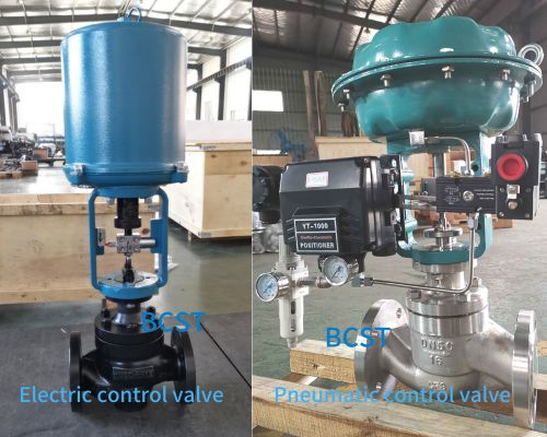
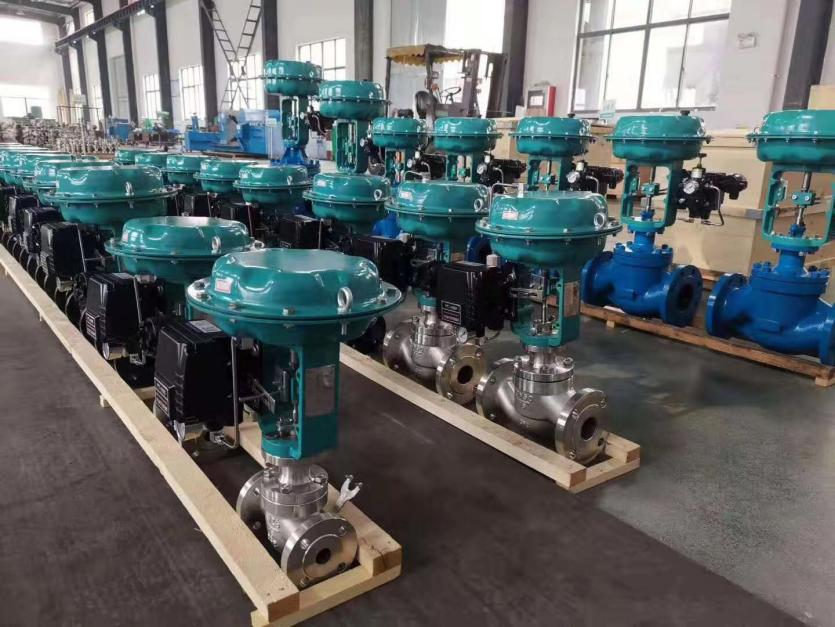
In control valve applications, electric and pneumatic control valves are quite common. They are widely used in various fields, such as industrial production, chemical engineering, petrochemicals, and more. Although their basic purpose is similar, they differ significantly in structure, working principles, advantages, and disadvantages. Users often need clarification about choosing the right type due to a lack of understanding of their differences. This article will provide a detailed comparison between electric and pneumatic control valves. Understanding their distinctions will make it clearer whether to opt for a pneumatic control valve or an electric control valve.
1. Different Working Principles
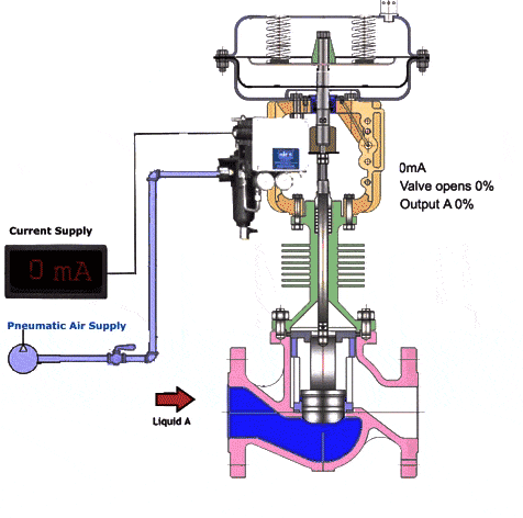
1.1 Pneumatic control valves operate using compressed air as the power source, with a cylinder as the actuator. They are driven by electrical valve positioners, converters, solenoid valves, and position-holding valves, among other accessories. The process usually involves connecting, installing, and debugging the pneumatic actuator and control valve. There are single-acting and double-acting for pneumatic actuator . Single-acting actuators have a reset spring while double-acting actuators do not. If a single-acting actuator loses its original position or suddenly fails, the valve can automatically return to its initial open or closed state.
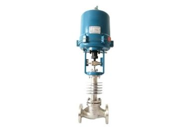
1.2 Electric control valves, on the other hand, are powered by 220VAC or 380VAC electric motors and controlled by a 4~20mA signal. Inside the control valve, a controller converts the current signal into a stepping motor’s angular stroke signal. The motor rotates, driven by gears, levers, or gears combined with levers, to operate the valve stem, achieving either linear or angular stroke motion. During operation, the motor runs, and the gear rotation generates a positioning signal for the valve through a sliding potentiometer at the three-way joint. The valve then receives signals from the industrial automation control system to drive the valve and adjust the cross-sectional area between the valve core and valve seat to control the pipeline medium’s flow rate, temperature, pressure, and other process parameters. This achieves automated control functionality.
2. Pneumatic Control Valve and Electric Control Valve Have Different Structures
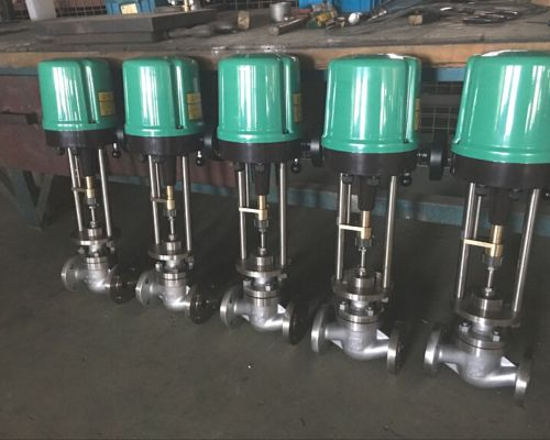
2.1 Electric Control Valve Structure
The electric control valve is driven by an electric motor. It consists of an electric motor, travel switch, actuator, valve body, valve seat, and valve stem. The electric control valve comes in three main structural forms: linear type, rotary type, and angular type.
In the linear type electric control valve, the electric motor drives the valve stem to move upward and downward, controlling the valve’s opening and closing.
The electric motor, reducer, and gears work together in the rotary-type electric control valve. The motor drives the gears to rotate, and the reducer then drives the valve stem to rotate, controlling the valve’s opening and closing.
The angular type electric control valve comprises an electric motor, reducer, worm wheel, worm, and valve body. The valve stem is driven to rotate by the worm wheel and worm reduction, controlling the valve’s opening and closing.
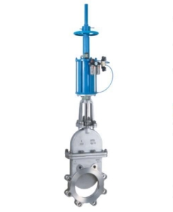
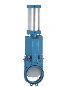
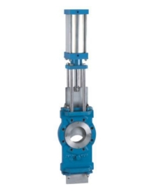
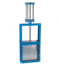
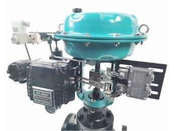
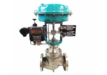
2.2 Pneumatic Control Valve Structure
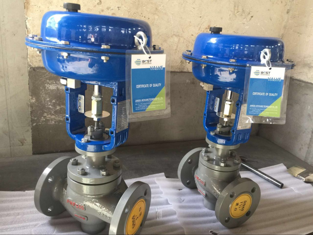
The pneumatic control valve is a type of control valve driven by compressed air. It comprises a pneumatic actuator, valve body, valve seat, and valve stem. The pneumatic control valve has two main structural forms: single-acting and double-acting.
The single-acting pneumatic control valve comprises a cylinder, valve cover, spring, and valve body. Compressed air from the gas guiding valve enters the cylinder, causing the piston to move up and down, driving the valve stem to control the valve’s opening and closing. When the gas supply is cut off, the spring reset the valve to its original position.
The double-acting type pneumatic control valve comprises a cylinder, valve cover, gas guiding valve, and valve body. Compressed air from the gas supply enters one of the two chambers in the cylinder, causing the piston to move forward or backward, driving the valve stem to control the valve’s opening and closing. When the gas supply changes direction, the piston in the cylinder moves in the opposite direction, this will return the valve stem to its original position.
3. Pneumatic Control Valve and Electric Control Valve Have Different Installation Principles
3.1 Installation Principles for Pneumatic Control Valve
The pneumatic control valve should be installed at a certain height from the ground, leaving enough space above and below for the valve disassembly and maintenance. It is essential to ensure easy operation, observation, and adjustment for control valves equipped with pneumatic valve positioners and handwheels.
The control valve should be installed on a horizontal pipeline and be perpendicular to the pipeline vertically. It is generally necessary to support the valve from below. In special cases where the control valve needs to be installed horizontally on a vertical pipeline, proper support should be provided (except for small-diameter control valves). During installation, avoid adding additional stress to the control valve.
1.The working environment temperature for the control valve should be within (-30 to +60) degrees, with relative humidity not exceeding 95%.
2.There should be straight pipe sections before and after the control valve, with a length at least 10 times the pipe diameter (10D) to avoid affecting the flow characteristics due to a short straight pipe.
3. When the diameter of the control valve differs from that of the processing pipeline, a reducing pipe should be used for the connection. For small-diameter control valves, threaded connections can be used. The direction arrow on the valve body should match the flow direction.
4. A bypass pipeline should be set up to facilitate switching or manual operation, allowing adjustment and maintenance of the valve without stopping the process.
5. Before installation, thoroughly clean the pipeline of foreign substances such as dirt and welding slag.
3.2 Installation Principles for Electric Control Valve:
The installation position, height, and inlet/outlet direction of the electric control valve must conform to the design requirements, and the connections should be secure and tight.
The electric control valve can be connected to the pipeline using various end forms. The main connection methods include threaded, flanged, and welded connections. When using flanged connections at temperatures exceeding 350°C, high-temperature resistant bolt materials should be selected to prevent bolt, flange, and gasket creep relaxation.
Before installing the electric control valve, a visual inspection must be carried out, and the valve nameplate should comply with the provisions of the current international standard GB12220, “General Valve Marking.” For valves with working pressure greater than 1.0MPA and serving as shut-off valves on main pipelines, strength and tightness tests must be conducted, and they can only be used if they pass the test. Other valves may not require separate tests and can be inspected during the system pressure test.
During the strength test, the test pressure is 1.5 times than the nominal pressure and it should be held for at least 5 minutes. The valve body and packing should have no leakage.
During the tightness test, the test pressure is 0.3MPa, and the test pressure should remain constant throughout the test duration, as specified in Table 2. The valve disc sealing surface should have no leakage to be considered qualified.
Nominal Diameter: DN15-500.
4. Pneumatic Control Valve and Electric Control Valve have different actuators.
4.1 The main considerations for selecting actuators are
① Reliability;
② Economy;
③ Smooth operation and sufficient output torque
④ Simple structure and easy maintenance.
A comparison of electric and pneumatic actuators: Electric actuators can only be used for intermittent operations, this makes them unsuitable for continuous closed-loop operations. On the other hand, pneumatic actuators have overload resistance and require no maintenance throughout their lifespan. They don’t need oil changes or other lubrication. Their standard service life can reach up to one million switch cycles, making pneumatic actuators superior to other valve actuators.
Safety
Pneumatic actuators can be used in potentially explosive environments, especially when dealing with the following situations:
· Needing explosion-proof valves (such as Namur valves with appropriate coils)
· Valves or valve islands requiring installation outside of the explosive area
· Pneumatic actuators used in the explosive area, driven by air hoses
· Electric actuators are costlier and unsuitable for use in potentially explosive environments.
Overload Resistance
Electric actuators will quickly reach their torque limits when additional torque or specific force requirements are needed. On the other hand, Pneumatic actuators demonstrate their overload resistance advantage, especially in cases where the valve actuator is periodically opened or closed for a long time, as deposits or sintering can increase starting torque. Using pneumatic components, increasing working pressure, force, or torque is easy.
Cost-effectiveness
In most water and wastewater treatment applications, valve actuators mainly operate in an on/off mode or even manually. Therefore, pneumatic components offer a promising rationalization prospect. Compared to electric actuators, which require monitoring functions like temperature monitoring, torque monitoring, conversion frequency, and maintenance cycles to be designed into the control and testing systems, pneumatic actuators don’t need any monitoring and control functions besides end position sensing and air source treatment. Pneumatic actuators have low costs, making automation of manual valve actuators more feasible.
Assembly
Pneumatic technology is straightforward. Installing pneumatic actuators on the valve drive head and connecting to the air source treatment device is easy. The maintenance-free design of pneumatic actuators ensures ease of use and ready-to-run capabilities.
Components
Pneumatic components have higher vibration resistance, sturdiness, and durability and are less likely to get damaged. Even high temperatures won’t damage corrosion-resistant components. Electric actuators consist of numerous components and are relatively more prone to damage.
Technology
Linear actuators directly act on the closing device, while swing actuators only need a piston and a driving shaft to convert “linear compressed air force” into swing motion. Using pneumatic actuators also allows for easy implementation of slow motion, achieved through simple and cost-effective flow control components. Electric actuators experience significant energy loss when supplied energy is converted into motion. This is primarily due to electric motors converting most of the energy into heat and using gearboxes.
5. Analysis of Pneumatic Control Valve and Electric Control Valve
In most industrial control applications, pneumatic control valves are commonly used. They are more economical than electric and hydraulic options because they utilize compressed air as the driving force. The simple structure makes them easy to handle and maintain. From a maintenance perspective, pneumatic control valves are easier to operate and calibrate, allowing for convenient on-site interchangeability.
One of their biggest advantages is safety. They are ideal for use in flammable and explosive environments when equipped with positioners. In contrast, non-explosion-proof or inherently safe electrical signals carry the potential risk of sparking and causing fires. Although electric control valves have gained wider application, pneumatic control valves still dominate in the chemical industry due to their inherent advantages.
However, pneumatic control valves do have some drawbacks. They exhibit slower response times, poorer control precision, and weaker deviation resistance due to the compressibility of gases, especially when using larger pneumatic actuators where cylinder filling and evacuation take time. Nevertheless, this may be fine for many industrial scenarios that do not require high control precision, ultra-fast response, or strong deviation resistance.
On the other hand, electric control valves find primary applications in power plants or nuclear power plants, where high-pressure water systems require smooth, stable, and gradual processes. Their main advantage lies in high stability and constant thrust available to users. The maximum thrust generated by electric actuators can reach up to 225,000 kgf, which is comparable to hydraulic actuators, but the latter are significantly more expensive. Electric actuators offer excellent deviation resistance, delivering a relatively constant thrust or torque output that can effectively counteract medium imbalances and achieve precise process parameter control. Consequently, they generally exhibit higher control precision than pneumatic actuators. When paired with a servo amplifier, it becomes effortless to achieve bidirectional interchangeability and set the fail-safe valve position state (hold/open/close). Electric actuators can remain in their original positions in case of a malfunction, whereas pneumatic actuators require a combination of protective systems for hold positions.
However, electric control valves have their drawbacks. Their structures are more complex, this makes them more prone to malfunctions. Due to their complexity, they require maintenance personnel with higher technical expertise. Frequent adjustments can lead to motor overheating, necessitating thermal protection, and may accelerate wear on reduction gears. Additionally, electric control valves operate slower than pneumatic and hydraulic actuators, taking longer to respond from the moment the controller sends a signal until the control valve moves to the corresponding position. This is an area where they lag behind pneumatic and hydraulic actuators.
6.Differences in the Application Scope of Electric Control Valves and Pneumatic Control Valves
6.1. Application Scope of Electric Control Valves are suitable for precise control in chemical, petrochemical, pharmaceutical, food, and light industries. They can handle various media and offer reliable operation with high control accuracy.
6.2. Application Scope of Pneumatic Control Valves are ideal for controlling large flow rates, low pressures, and general media in industries like metallurgy, chemical, textile, papermaking, water treatment, and pharmaceuticals. They are known for the easy operation, affordability cost , and high reliability performance.
In conclusion, both electric control valves and pneumatic control valves have their pros and cons. The choice should be based on specific application requirements. Factors such as control precision, flow rate, working pressure, and the type of medium should be considered to select the most suitable control valve.
7. BCST’s Recommendations for Selecting Pneumatic and Electric Control Valves
(1) it is recommended to use imported electronic actuators with domestically manufactured valves for domestication purposes or new projects.
(2) Diaphragm actuators have limitations such as insufficient thrust, low stiffness, and large size, but they are still the most widely used actuators, due to their simple structure.
(3) Considerations for piston actuators:
· When the thrust of pneumatic diaphragm actuators is inadequate, choose piston actuators to increase the output force. For large differential pressure control valves (e.g., medium-pressure steam cut-off valves), when DN≥ 200, even double-acting piston actuators might be needed.
· For regular control valves, piston actuators can be used as a replacement for diaphragm actuators, significantly reducing the size of the actuator. From this perspective, the usage of pneumatic piston control valves is expected to increase.
· For angular-stroke control valves, the typical structure of the actuator is a dual-piston gear-rack rotation type. It’s worth emphasizing that the traditional “linear-stroke piston actuator + angle iron + crank connecting rod” approach is still widely used.