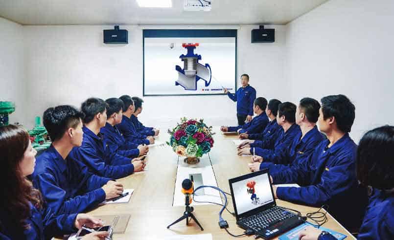
Today, let me show you how a pneumatic globe control valve is produced at the BCST valve factory
· 1. Order is confirmed
Once the order is confirmed, the client’s advance payment reaches our account, the order will carry formally.
· 2.Technical Communication
Firstly, there will be a technical meeting between our technical department, Engineers would select the suitable valve material, body structure, and check which raw material is in stock, which spares part need purchase outside. And report this information to the inner ERP system. Meanwhile, the valve drawing and inner dimension need to be made and the CV calculation sheet needs to be calculated by the software.
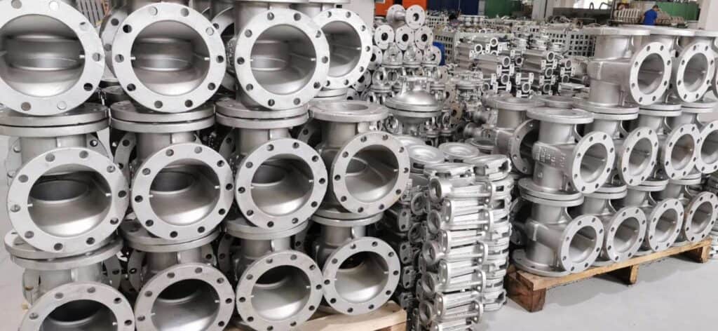
3.Control valve body selection and process
The body part of the control valve is contacting with the measured liquid. To regulate the flow, temperature, the pressure of the fluid, such as oil, steam, water, the engineer needs to select the right material, CV (coefficient of the valve). , and structure, etc.
What is the technical parameter which affects the control valve body selection?
1.Measured Medium If the medium is corrosive, there should be a PTFE liner or special material for the body. If the medium is food standard, the body material should be 304 or 316SS and sanitary standard.
2.Working pressure, the working pressure is close to the body structure, if working pressure is high, the caged type may be used. And the body thickness is also affected by working pressure, BCSTmax working pressure can reach 2500#.
3.Working temperature, if the working temperature is over 250 °C, it belongs to a high-temperature structure, the packing will be selected high-temperature type, and the seal will be a metal seal, instead of a soft seal. BCST max working temperature is 560 °C
4. Pipe size , Pipe size is close to valve size, if the valve size need to reduce, it should consider pipe size
5.. Flow capacity, flow capacity is the important factor which affects the body size. An undersized valve will slow down fluid or cause inefficiency in the fluid system, while an oversized valve can be a kind of waste in the control system. It’s important to select a maximum flow capacity for your application and choose the valve size with enough capacity.
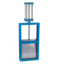
The following control valve body is the common structure.
2 way have one INLET and one OUTLET port and, upon actuation, allow media to pass through (known as a 2-way Normally Closed), or to stop the flow (2-way Normally Open)
3-way valves add a third port to allow for exhausting pressure at the OUTLET port when the INLET port is blocked. 3-Way valves are offered Normally Closed or Normally Open, as well.
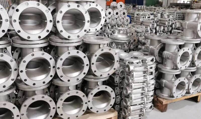
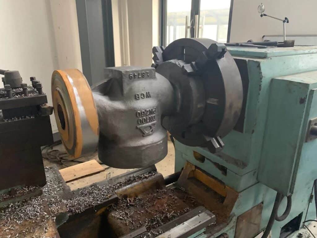
After the suitable body is ordered and purchased from the foundry factory, they will need to process by CNC machine, then they need to do a pressure test to check whether there is leakage on the body. If the body is a defective one, it needs to remake a new body. And after they pass the quality checking, they will move to the next steps
4.Control valve trim
What is the control valve Trim?
Valve Trim includes the internal wetted part of the valve body, which contains stem, seating material, package, disc, plug, back rings, etc. Any wetted parts that can be removable and replaceable in the valve body are a part of the control valve trim.
The valve body, a bonnet that comes in contact with process liquids is not considered as trims.
Valve components such as back seals, O-rings, bushings, packings, etc., vary with the type of valve such as Ball valve, butterfly valve, etc. Control valves are available for betterflow regulation applications in liquid service control applications.
Some part which is also a part of a control valve trim are as follows.
Plug: The plug is a tapered or conical shape that fits into aPlug: The plug is a tapered or conical shape that fits into an orifice hole the size of the largest dimension of the closed plug. The position of the plug is proportionate to the flow by the valve when fully up or open and down or closed,. Based on the flow characteristics required, there are various shapes of the plug.
Cage: It is a part of a valve trim that encloses the closure member and may provide flow characterization. Cage may also be helpful to guiding, balance, stability, proper calibration, and assist the assembly of other parts of the valve trim.
Seat: control valve seat are the seat and closure member sections that are contacted with each other for closure. Because the seats are subject to wear during the seal making process, the seatings scalability is likely to to decrease during daily operation. For control valve seat , there are metal seating and soft seating , their leakage level are differential.
Stem: Depending upon the control valve design, the plug and stem may be a single one or threaded into the plug. Valve stems are the same materials as the plug material .
Test valve trim at 2500# rating and high temperature at BCST factory
Packing: Packing is to prevent damage to the stem. Bad packing leads to leakages of fluid or gases to happen. If packing is loose, there is a chance of leakage. If it is tight, is hard to move.
Trim selection against Corrosion & Erosion
How to choose a suitable valve trim material depends on service conditions which are include high temperature, pressure, chemical composition, fluid velocity, liquids with suspended solids, etc.
There are many corrosion resistance tables, used to determine the sustainability of the material to resist corrosion. The second one is erosion, a material that can withstand corrosion may not be suitable for erosion issues.
Erosion is caused by high-velocity liquids with abrasive particles harder than trim material.
Metallic Trim Material
The most common trim material is AISI type 316 stainless steel. The metallic trim is good for all-around choice in general service for about -195 Deg C to +400 Deg C and moderately corrosive fluids. Alloys of steel, titanium.
Cobalt-Chromium alloys, Nickel-Boron alloys. Cobalt coated ball valves to overcome corrosion and erosion.
Non-metallic Trim Material
Operating temperature is most important in selecting nonmetallic trim material. Poly tetra fluoro ethylene (PTFE), Teflon, etc.
Anti-cavitation and Noise Trim
One of the reasons for noise generation in control valves is a result of cavitation. Control valves with anti-cavitation trim can overcome the problems in water service applications. Damage done to a control valve by cavitation is a serious issue.
Special Design Trim
Special design cage guided trims can control cavitation effectively.
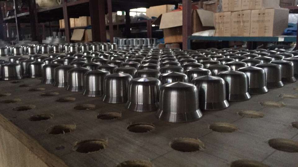
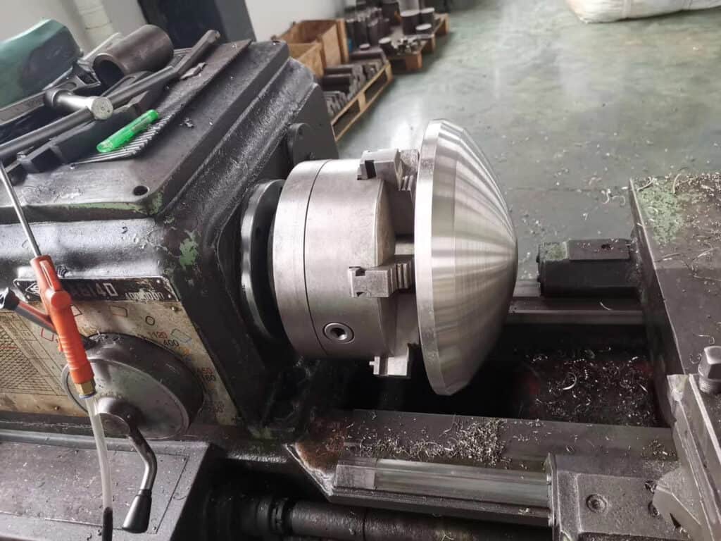
Below is the picture and video for our trim process and trim in stock
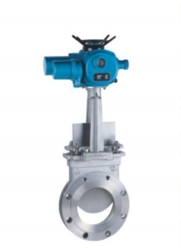
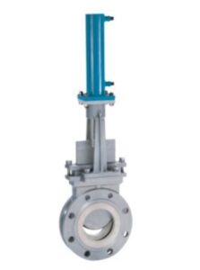
5.Control valve actuator
An actuator is a device installed to the control valve which provides power for driving the control valve. It mainly acts as two functions
1. Drive the moveable parts to a position required by the control signal
2. Supply default positioning when there is no drive power available.
There are mainly three types of actuators that are widely used.
1. Pneumatic
2. Electric
3. Hydraulic
About how to select the suitable actuator, please see our blog What kind of actuators are commonly used for the control
6.Control Valve assembly
Once the control valve body, trim, actuator are ready, the next step is the assembly of all the parts.
Control Valve Inspection and Test
After the control valve is assembled, the test should be carried
Fire test: In some industries, such as the petrochemical and natural gas industry, there is the potential danger of fire, the valve should be specially designed to make them still have good sealing and operating performance under high-temperature fire. A fire safe test is an important way to measure the fire resistance of the valve.
Visual Test as per MSS SP-55, the completed valve assembly will be visually inspected for general workmanship, including cleanliness, scale, identification, protective coatings, and conformance to purchase specifications. Valve body castings should be visually inspected for obvious defects or flaws.
Dimensional Test:
Face-to-face dimensions should be checked as per ANSI/ISA-75.08.01, ANSI/ISA-75.08.06, and ASME B16.10.
Flange facings and dimensions as per ASME B 16.5
Inspection of Body Marking as per ASME B 16.5, ASME B 16.34, and MSS-SP 25.
Chemical analysis and mechanical properties as per the applicable ASTM material code and EN10204 3.1
Nondestructive test as per ASME B 16.34
Hydrostatic test follows ASME B 16.34 or MSS-SP61
Seat leakage test as per ANSI/FCI 70-2.
Functional and Performance test (i.e.
hysteresis plus Deadband, linearity, repeatability, etc) as per IEC 60534-4 and ISA 75.13.01
For electrical accessories (such as solenoid valve, I/P positioner, position transmitter, etc): Check the healthiness of I/P converter . Position feedback transmitter,airlock relay, solenoid valve, and air supply pressure.
Functional Test
Check the manual operation of the valve using the handwheel. Stroke the valve either from local or from DCS as applicable. Confirm the valve travel from local.
How control valve produce in BCST valve factory
7. Valve Calibation
How to calibrate the control valve ?
Please follow below steps
Firstly, Calibrate the Valve with the inbuilt option like “Auto Calibration” available in the valve positioner. Also, check the Limit switches function and adjust them as required.
If it is the SMART Control Valve, we will use a HART communicator to calibrate the control valve. Give the supply pressure according to the valve as per nameplate details. Connect the HART to the valve positioner.
Then go to valve simulate command, enter 0% and observe the valve position.
Next, enter 25% in HART and observe the valve travel position.
In the same way, enter 50%, 75% and 100% in the HART communicator then observe the valve stem travel position accordingly.
You can find a manual scale (0% to 100%) with a needle on the valve to verify the valve travel position.
Electrical type and routine test as per IEC 61010-1
All calibration shall be performed in accordance with written procedures that comply with the applicable standards.
Pressure Tests
Usually, the testing pressure is 1.5 of the working pressure
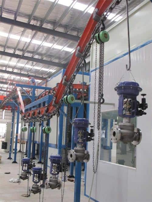
8.Control Valve Bodypainting
Valve body painting is designed to delay exterior corrosion
Usually, if the valve body is painted black or silver color, the stainless steel valve body is not painted at all. If the end-user needs another color, it is also no problem. BCST valve painting is based on the American Petroleum Institute (API) 600
Surface Reparation
Proper surface preparation is important for the successful application of any coating. Rust, grease, oils, and dirt are removed before any coating . The surface may be prepared either chemically or mechanically. Mechanical surface preparation includes removing surface flaws by water or blasting way . Various paints require different surface finishes to cling properly.
Paint preparation
Grinding pigment paste to join makings, solvents,other additives to reach the paint quality requirements
Usually, the paint contains the below elements
1.Pigments, which provide not only the coloration, but also help with corrosion resistance and the overall strength of the coating or paint mixture
2.Additives, including thickeners, UV stabilizers, and anti-foaming agents
3.Resins, which are acrylic and epoxy that bind all the components together into a homogeneous substance
4.Solvents that affect the drying time and viscosity of the paint mixture
Coating
BCST valve painting is mainly used power coating
What is power coating ?
Powder coating is an electrostatically applied and baked‐on finish consisting of a mixture of finely ground resin, pigments, and binders, which is similar to wet‐spray coatings. Different with wet‐spray coatings, powder coating is almost 100% without VOC , so reducing some of the environmental concerns compared with wet‐spray coatings. Powder coating is our standard finish for actuator casings, yokes, and cylinders, cast iron , as well as carbon steel valve body assemblies in our factory .
During the powder coating process, the part is cleaned, and a conversion coating is formed on the substrate. A seal coat is applied over the conversion coating. These steps help the part surface for the application of the powder coating and improve the adhesion of cured powder to the part.
This pretreatment process is the foundation for the powder coating and is critical in assuring the durability of this coating in corrosive environments
First coat : anti corrosive paint ,Total dry film thickness: 60 to 76.2 microns (2.5 to 3.0 mils) minimum , working temperature limit is 121C (250F) constant, 149C (300F) in intervals
Second coat: Powder Coating, Total dry film thickness: 50 microns (2 mils) minimum, working temperature limit is 121C (250F) constant, 149C (300F) in intervals
If the application is high temperature or corrosive, there will be a third coating, Zinc-rich primer with silicone modified top coats, Typical total dry film thickness: 100 to 275 microns (4 to 11 mils), its temperature limit is 537C (1000F) constant, 648C (1200F) in intervals
BCST valve coating is based on ASTM B117
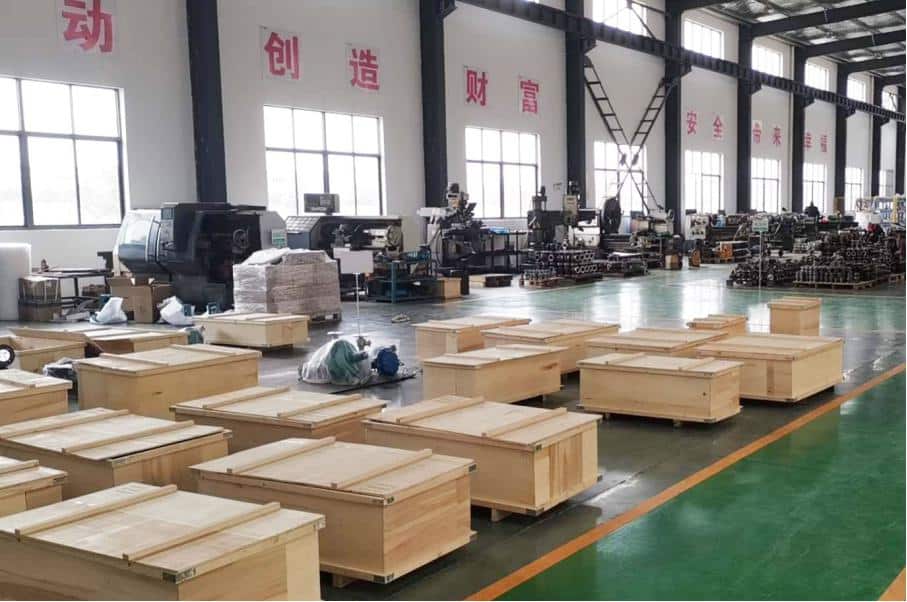
9.Packing and Delivery
BCST valve packing is used exported wooden box with good protection.